33
Bellfires
English
Instructions for use and installation instructions
(**) : ( Y
1
+ Y
2
) : ( X
1
+ X
2
) > 2 : 1
(vertical to horizontal ratio (or 45° upwards) is always at least 2 to 1) )
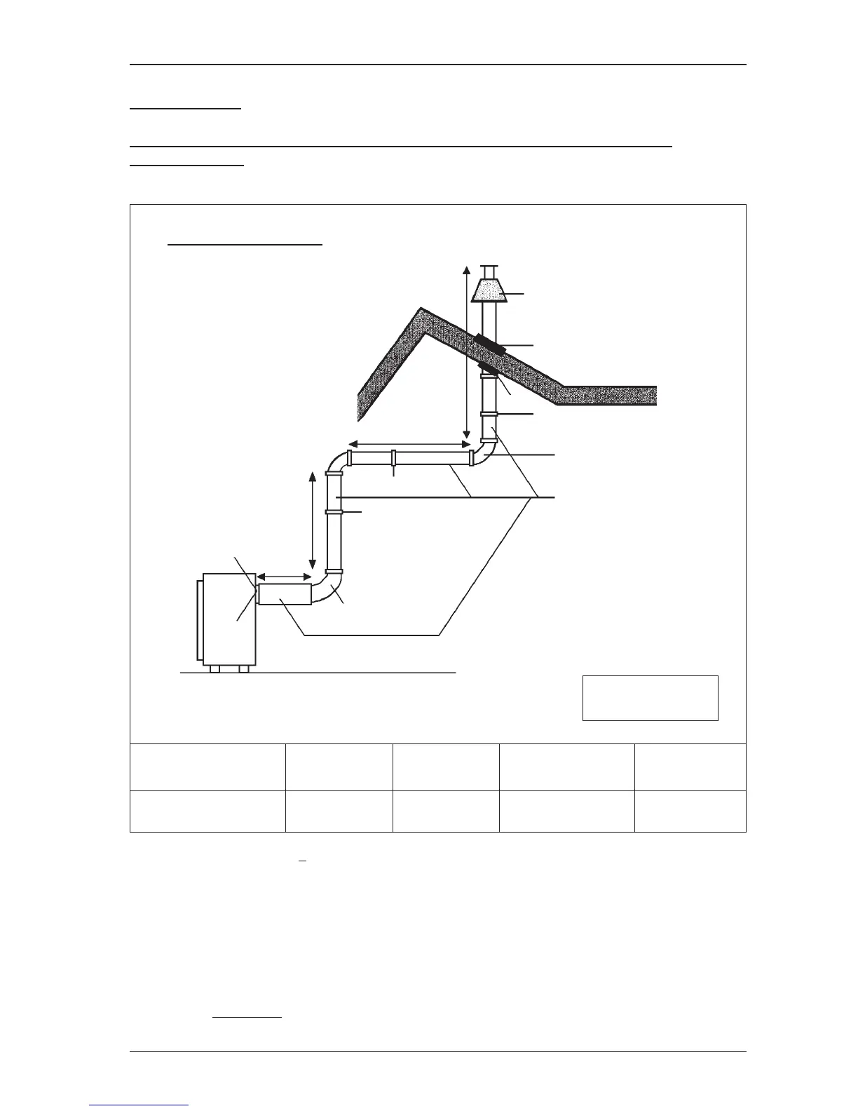
ALL SIZES INCLUDE THE LENGTH OF THE ROOF OR WALL TERMINATION
Figure 18: Vertical roof-mounted outlet with bend
SMART - BELL
RIGID CONCENTRIC FLUE Ø100 mm - Ø150 mm SYSTEM CONNECTION
POSSIBILITIES
REAR CONNECTION
Appliance: Distance X
1
(**) Distance X
2
(**) Distance Y
1
+ Y
2
(**)
(min.-max.) (min.-max.) (min.-max.)
Smart Bell 0 - 0,5 m 0 - 2,0 m 1,0 - 11,0 m -
16
17
24
23
10, 11, 12, 13
23
23
2
14, 15
4
28
14, 15
Y
2
Y
1
X
2
X
1
Item descriptions:
see 3.4.2
Assemble
restriction plate