42
Bellfires
English
Instructions for use and installation instructions
Important: Using the hand, screw the thermocouple connection (and
thermocouple interrupter) into the back of the gas regulating
unit. Carefully tighten another half of a turn using a number 9
fork spanner. See figure 25, 26 and Chapter 6.
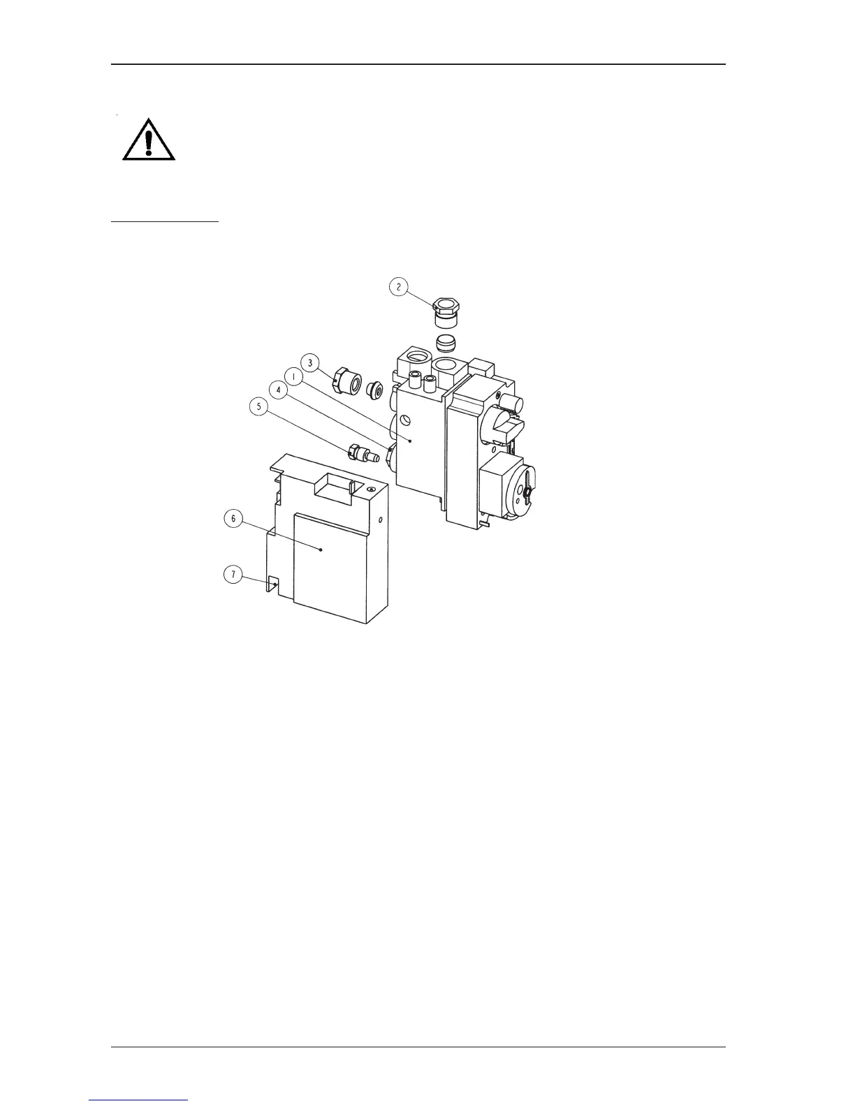
Remote control
Gas regulating block and receiver in operating unit
Figure 25: Remote control: Gas regulating block and receiver in operating unit
1 Gas regulating block
2 Gas supply connection 3/8” - Ø12 / Ø15 mm insertion
3 Burner piping connection Ø8 mm insertion
4 Thermocouple connection M 9x1 mm insertion
5 Pilot light piping connection Ø4 mm insertion
6 Receiver
7 Piezo cable connection