INSTALLATION
STEP 2 : CONNECT TO GAS SUPPLY
Means of isolation shall be provided at the
shutoffpointbyeitheranapprovedquick
connect device or a Type 1 manual shut
offvalve.Theoutletofthequickconnect
device shall be at, or below, the horizontal
position.
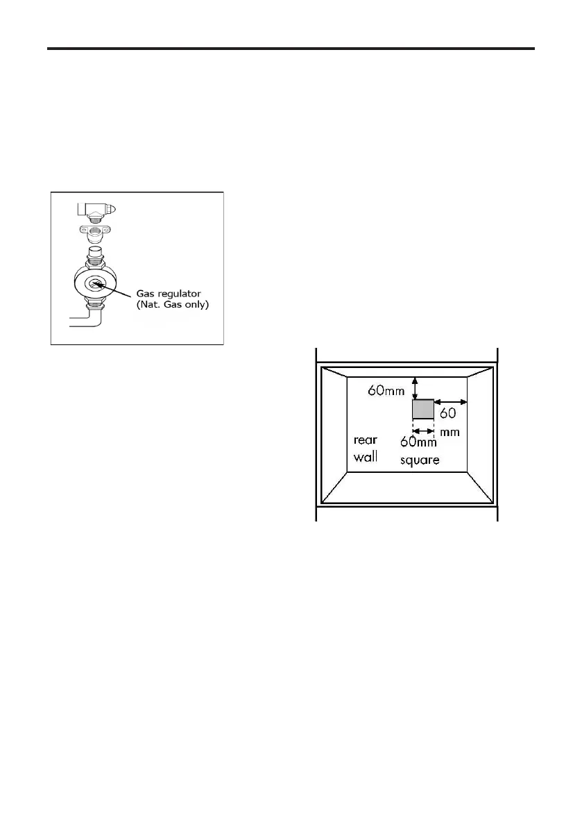
Connection to the gas supply should be
madeusingtheAquaknectAS/NZS1869
class B hose assembly with an internal
diameter of not less than 10mm and regu-
lator (regulator for use with natural gas)
NOTE:Maximumlengthofhose900mm.
The temperature rise of the areas at the
rear of the cooker that are likely to come
intocontactwiththeexiblehosedonot
exceed70˙C.
1. The inlet to the appliance is ISO 7
- Rp ½” internal thread situated towards
the top right hand rear corner.
2. Fit the bayonet connection to the wall
in shaded area as shown.
The shaded area shown is applicable to
installations in minimum depth cabinets.
If more room is available, the bayonet
xingareacanbeextended,providedthat
theexibletubedoesnotobscurethefan
intake.
3. Use a 900mm - 1125mm length of
exibleconnector.Theexibleconnector
shallbettedsuchthatitcannotcome
into contact with a moveable part of the
housing unit (e.g.; drawer) and does not
pass through any space susceptible of
becoming congested. Make sure that the
exibleconnectordoesnotblockthecool-
ing fan inlet.
4. Natural gas installations must con-
form to local codes or, in the absence of
localcodes,withAS:5601aswellasthe
requirementsofanylocalcouncil,gas,
electricity authority or other statutory
regulation.
5. Rigid connections must be accessible
to disconnect for servicing. Cut a 150mm
squareholeintherighthandrearcorner
of the support shelf for the supply pipe.
6. Make sure all connections are gas
sound.
Pressure test point
Thepressuretestpointisttedonthe
outlet of the regulator or on an adapter
whichshouldbettedontotheoutletof
the regulator.
 Loading...