200663_03 Page 2
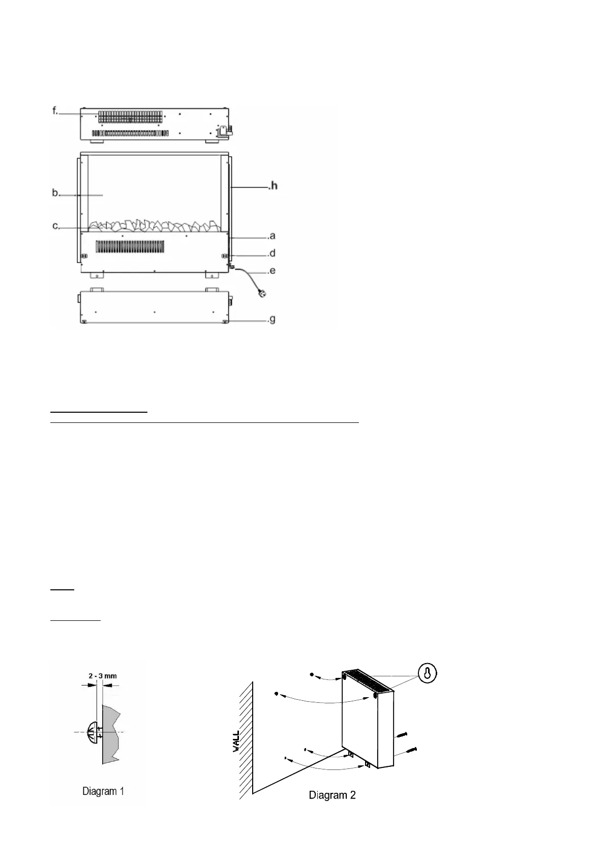
Description of the appliance (Fig. A)
a. Switches d. Front Panel Clip lock
b. Flame effect Screen e. Power Cord
c. Fuel bed f. Air Outlet
g Front Panel Hanging slots h. Backlights
Installation Procedure
NB for Deflector Bracket fitting please see additional instruction leaflet
a) Affix the wall brackets to the lower part of the back of the fire unit using the 4 small screws as supplied.
b) When you unpack the front panel, you will find a template. Attach the template carefully to the wall in the chosen position,
taking note of the minimum clearance distance for each type of front panel stated on the template. (See diagram 4,
Diagram 5 if using the Deflector Bracket as the clearances at the bottom of the fire are different)
c) Drill the 4 fixing position using an 8mm drill bit for the wall plugs supplied or drill the correct size for alterative chosen
fixings if required for the type of wall. (See important note on page 2).
d) Remove the template paper.
e) Install the 2 top fixings into the wall and then install the 2 long screws, screwing them in so the underside of the screw
head stands off the wall by 2 to 3 mm. (See Diagram 1).
f) Locate the heater on the two keyhole slots in the back panel onto the 2 top fixing screws and secure the heater by fixing
the remaining 2 long screws through the lower fixing brackets (See Diagram 2).
g) To fit the front panel, raise the panel into position and locate the returns on the top of the two fixing brackets into the
corresponding hanging bracket slots on the top of the heater (See Diagram 3). Push the bottom of the front panel firmly
into position on the lower clip locks.
Note: The lower support brackets must always be used so as to prevent the heater lifting from the wall mounting bracket.
IMPORTANT If the screws & wall plugs are not suitable for the type of wall, the fixings that are used must be strong enough
to support the weight of the fire & the front panel.