EasyManua.ls Logo

BENDIX E-10 DUAL BRAKE VALVES User Manual

BENDIX E-10 DUAL BRAKE VALVES
8 pages
To Next Page IconTo Next Page
Page #1 background imageLoading...
Page #1 background image
1
®
SD-03-817
Bendix
®
E-6
& E-10
Dual Brake Valves
DESCRIPTION
The E-6
(Figure 1) and E-10
(Figure 2) dual brake valves
are floor mounted, treadle operated type brake valves with
two separate supply and delivery circuits for service (pri-
mary) and secondary braking, which provides the driver with
a graduated control for applying and releasing the vehicle
brakes.
The E-10
dual brake valve (Figure 2) is similar to the E-6
dual brake valve except that a metal coil spring housed in
an upper body assembly replaces the rubber spring used in
the E-6
valve. The use of a metal coil spring (and the upper
body assembly) provides greater treadle travel and, there-
fore, provides the driver with a less sensitive "feel" when
making a brake application. The E-10
dual brake valve is
generally used on buses, where smooth brake applications
contribute to passenger comfort.
The circuits in the E-6
/E-10
dual brake valves are identified
as follows: The primary circuit is that portion of the valve
between the spring seat which contacts the plunger and the
relay piston; the secondary circuit is that portion between
the relay piston and the exhaust cavity.
The primary circuit of the valve is similar in operation to a
standard single circuit air brake valve, and under normal
operating conditions the secondary circuit is similar in
operation to a relay valve.
Both primary and secondary circuits of the brake valve use
a common exhaust protected by an exhaust diaphragm.
OPERATION
APPLYING: NORMAL OPERATION - PRIMARY
CIRCUIT PORTION
When the brake treadle is depressed, the plunger exerts
force on the spring seat, graduating spring, and primary
piston. The primary piston, which contains the exhaust valve
seat, closes the primary exhaust valve. As the exhaust valve
closes, the primary inlet valve is moved off its seat allowing
primary air to flow out the primary delivery port.
FIGURE 1 - E-6
DUAL BRAKE VALVE
FIGURE 2 - E-10
DUAL BRAKE VALVE
3/8” P.T.
PRIMARY
DELIVERY
3/8” P.T.
PRIMARY
SUPPLY
3/8” P.T.
SECONDARY
DELIVERY
EXHAUST
3/8” P.T.
SECONDARY
SUPPLY
TREADLE
MOUNTING
PLATE
3/8” P.T.
PRIMARY
SUPPLY
3/8” P.T.
SECONDARY
SUPPLY
3/8” P.T.
PRIMARY
DELIVERY
EXHAUST
3/8” P.T.
SECONDARY
DELIVERY
MOUNTING
PLATE
TREADLE
BOOT
Question and Answer IconNeed help?

Do you have a question about the BENDIX E-10 DUAL BRAKE VALVES and is the answer not in the manual?

BENDIX E-10 DUAL BRAKE VALVES Specifications

General IconGeneral
BrandBENDIX
ModelE-10 DUAL BRAKE VALVES
CategoryControl Unit
LanguageEnglish

Summary

Description of Dual Brake Valves

E-6 and E-10 Valve Overview

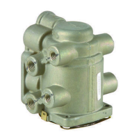
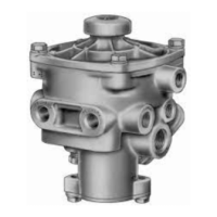
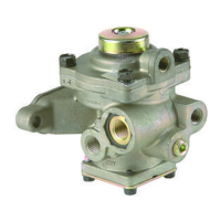
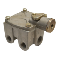
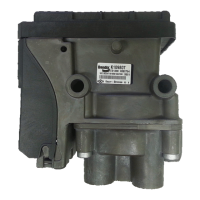
Introduces the E-6 and E-10 dual brake valves and their basic function, noting differences.

Circuit Identification

Defines the primary and secondary circuits within the dual brake valves for service and secondary braking.

Dual Brake Valve Operation

Applying: Normal Operation - Primary Circuit

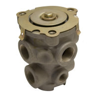
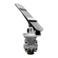
Explains how the primary circuit functions when the treadle is applied, closing exhaust and opening inlet.

Applying: Normal Operation - Secondary Circuit

Details the secondary circuit's operation during normal brake application, moving the relay piston.

Applying: Loss of Air - Secondary Circuit

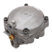
Describes primary circuit function when secondary circuit loses air pressure.

Applying: Loss of Air - Primary Circuit

Explains secondary circuit operation when primary circuit loses air pressure.

Balanced: Primary Circuit

Defines the balanced state for the primary circuit when delivery pressure equals pedal force.

Balanced: Secondary Circuit

Defines the balanced state for the secondary circuit when delivery pressure matches primary.

Releasing: Primary Circuit

Explains how air is exhausted from the primary circuit upon treadle release.

Releasing: Secondary Circuit

Explains how air is exhausted from the secondary circuit upon treadle release.

Preventive Maintenance

Service Checks and Procedures

Operating Check

Details checking delivery pressure proportionality and fall-off during treadle movement.

Leakage Check

Describes the procedure for checking brake valve leakage using a soap solution.

Removal

Instructions for removing the brake valve and treadle assembly from the vehicle.

Disassembly

Step-by-step instructions for disassembling the E-6 and E-10 dual brake valves.

Component Servicing

Cleaning and Inspection

Procedures for cleaning metal parts and inspecting components for wear or damage.

Assembly

Instructions for reassembling the dual brake valve components, including lubrication.

General Safety Guidelines

Related product manuals