4
Auxiliary I/O Connector
An optional auxiliary connector provides a connection to
the MC-30
™
controller auxiliary feature I/O pins. The fi ve
auxiliary ground-switch inputs and two auxiliary outputs can
be activated and confi gured with a diagnostic tool.
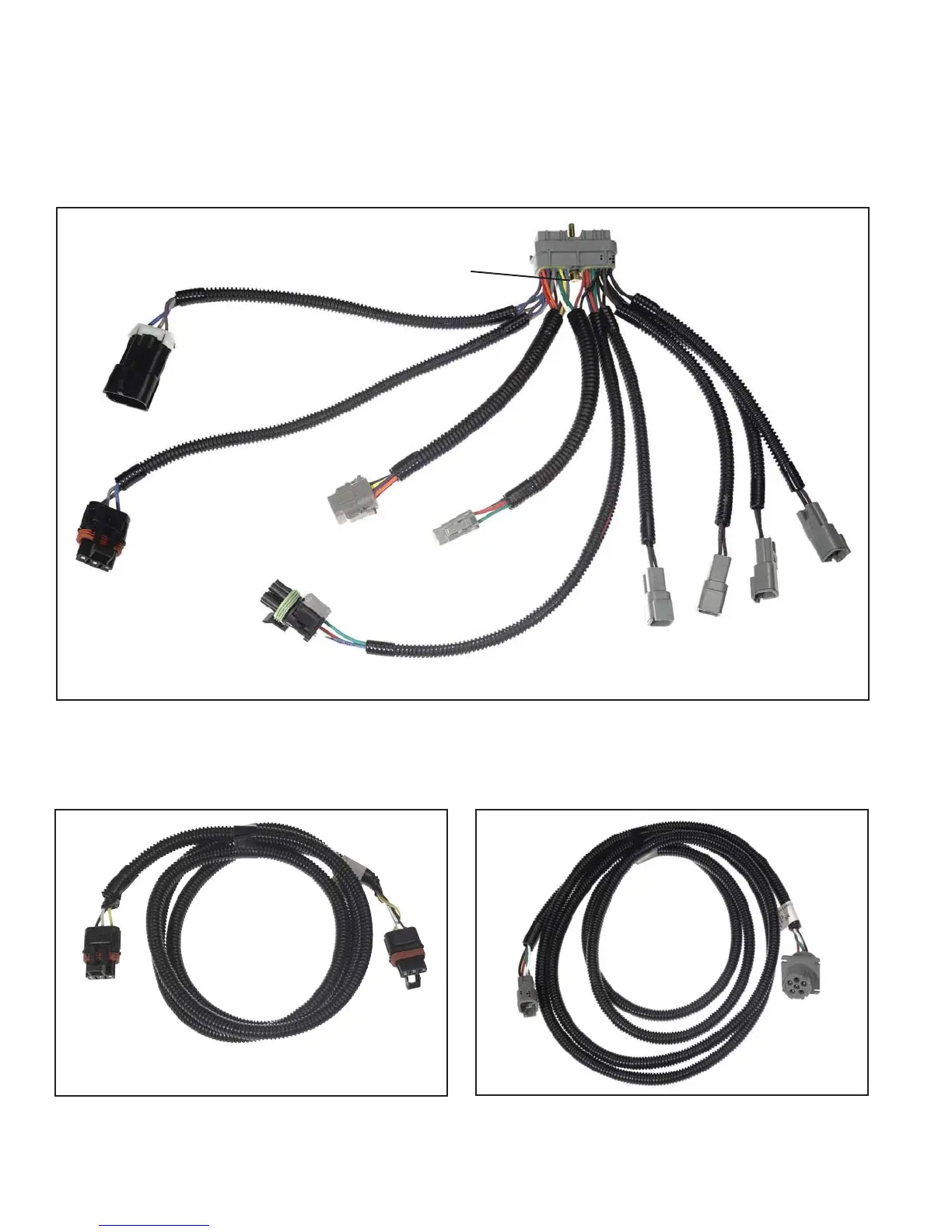
FIGURE 5 - MC-30
™
CONTROLLER PIGTAIL HARNESS (4S/2M WITH DIAGNOSTIC AND AUXILIARY CONNECTORS
SHOWN)
30-Pin ECU
Connector
8-Pin Auxiliary
(AUX)
3-Pin Modulator 2
(MOD2)
3-Pin Modulator 1
(MOD 1)
4-Pin Diagnostic
(DIAG)
5-Pin Power and
Indicator Lamp
(PWR/WL)
2-Pin Wheel
Speed Sensors
ECU Connector Jackscrew
(Tighten to 15-20 in. lbs.)
Left Rear
(LFT RER)
Right Rear
(RHT RER)
Left Front
(LFT FRT)
Right Front
(RHT FRT)
FIGURE 6 - REMOTE MODULATOR HARNESS (MOD2)
Modulator 2
(MOD2)
To
Pigtail
FIGURE 7 - REMOTE DIAGNOSTIC HARNESS
To
Pigtail
To Diagnostic
Tool
POWER AND GROUND
Trailer electrical power is supplied to the MC-30
™
controller
from the ignition and brake light circuits. Note: The MC-30
™
controller may not function properly when powered with a
battery charger. See Chart 2.