6
Wheel Speed Sensor Adjustment
Speed sensors are properly adjusted by gently pushing
(not striking) the sensor into the clip until it makes contact
with the face of the tone ring. The wheel speed sensor
will automatically adjust as the wheel rotates. If rotating
the wheel causes a gap of 0.020 in. or greater, check for
excessive wheel bearing play or tone ring runout. Proper
wheel speed sensor installation is critical to proper ABS
operation. See Figure 10.
M-30T
™
ABS MODULATOR-VALVES
The M-30T
™
Bendix
®
trailer ABS modulator-valve is
controlled by the EC-30T
™
controller to modify driver applied
air pressure to the service brakes during ABS activation. The
ABS modulator-valve is an electro-pneumatic control valve
and is the last valve that air passes through on the way to
the brake chambers. The hold and exhaust solenoids of the
M-30T
™
modulator-valve are activated to precisely modify
the brake pressure on command. The EC-30T
™
controller is
designed to control one or two modulator-valve assemblies.
See the MC-30
™
controller’s electrical system schematic
for ABS modulator connector pin locations, Figure 16.
The M-30T
™
modulator-valve is available in two mounting
confi gurations.
FIGURE 11 - M-30T
™
TANK (NIPPLE) MOUNT
MODULATOR-VALVE
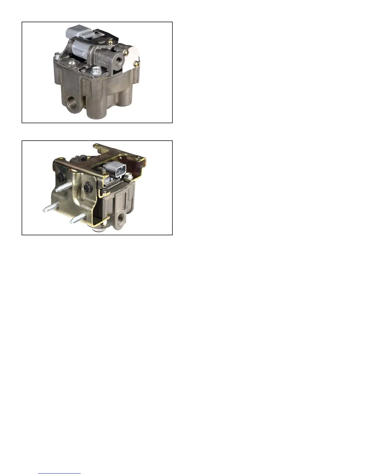
FIGURE 12 - M-30T
™
BRACKET (FRAME) MOUNT
MODULATOR-VALVE
Tank (Nipple) Mounted
The M-30T
™
modulator-valve tank-mount assembly is
mounted by using a schedule 80 (heavy gauge steel) 1/2"
nipple directly between the trailer supply tank and the
M-30T
™
modulator-valve supply port. A tank with a
reinforced port must be used. See Figure 11.
Bracket (Chassis) Mounted
The M-30T
™
modulator-valve bracket mount assembly is
mounted directly to the trailer frame rail or crossmember.
See Figure 12. The bracket studs are secured using
three 5/16-18 nuts and lock washers torqued to 180-220
in-lbs.
J1708/J1587 DIAGNOSTIC LINK
The MC-30
™
controller provides a J1708/J1587 diagnostic
link with data and power to communicate with the vehicle
and various diagnostic tools. Diagnostics, testing,
confi guration, data transfer and other functions can be
performed using this link. The MC-30
™
controller is
supported by diagnostic tools such as the MPSI Pro-Link
®
and Bendix
®
ABS Diagnostic Software. Ignition power must
be provided to the MC-30
™
controller for the diagnostic link
to be active. See the MC-30
™
controller electrical system
schematic for J1708/J1587 diagnostic link pin locations,
Figure 16.
AUXILIARY I/O
Auxiliary Function Inputs
The MC-30
™
controller offers fi ve auxiliary ground switch
inputs. These inputs can be configured for various
custom functions using a diagnostic tool. See the
MC-30
™
controller’s system electrical schematic for auxiliary
function input connector pin locations, Figure 16.
Auxiliary Function Outputs
The MC-30
™
controller offers two auxiliary output drivers.
These outputs can be configured for various custom
functions. Pin F1 of the 30-pin connector is the auxiliary
low side output. Pin K2 of the 30-pin connector is the
auxiliary high side output.
MC-30
™
CONTROLLER POWER-UP
SEQUENCE
At power-up, the MC-30
™
controller performs a series of
self-checks that can assist a technician in determining the
status and confi guration of the system.
Trailer ABS Indicator lamp
At power-up without detected faults, the trailer ABS
indicator lamp will illuminate for 2.5 seconds as a bulb
check and then turn off.