8
2S/1M Axle Dolly-Axle
2S/2M Axle Side
4S/2M Axle Side
SELF-CONFIGURATION / CONTROL TOGGLE
When activated with a magnet or diagnostic tool, the
self-confi guration feature allows for wheel speed sensor,
modulator and ABS control settings to be altered. This
is generally performed after replacement of an MC-30
™
controller. See chart 5.
CAUTION: An incorrect ABS confi guration may cause
a fault indication or degraded ABS performance. All
MC-30
™
controller’s service replacement parts are
initially defaulted to 4S/2M side control and may need
to be reconfi gured upon installation. Before and after
activating a self-configuration, always determine
the current ABS configuration by monitoring the
diagnostic LEDs at power-up or by activating blink
code diagnostics.
Wheel Speed Sensors
The MC-30
™
controller will self-confi gure for either two
or four wheel speed sensors. If either rear (RER) wheel
speed sensors are detected, four wheel speed sensors
will be selected. If neither rear wheel speed sensors are
detected, the MC-30
™
controller will confi gure for two wheel
speed sensors. The MC-30
™
controller will default to two
ABS modulators for any four sensor confi guration.
When confi gured for two wheel speed sensors, Right Front
(RHT FRT) and Left Front (LFT FRT) wheel speed sensor
inputs must be used, even if the wheel speed sensors are
not physically located on the front axle.
Modulators
The EC-30T
™
controller will self-confi gure for either one or
two modulators. The EC-30T
™
controller will automatically
confi gure for two ABS modulators if it detects Modulator 2
(MOD2) and/or either of the rear wheel speed sensors. If
MOD2 is not detected and no rear wheel speed sensors
are detected, the EC-30T
™
controller will confi gure for a
single ABS modulator.
When confi gured for a single modulator, Modulator 1 (MOD
1) must be used.
ABS Control Toggle
The MC-30
™
ABS controller control setting can be toggled
between Control Group A and Control Group B. When
activated, the MC-30
™
controller will toggle the ABS control
between (axle control) and (dolly-axle control or side
control). When a self-confi guration occurs without an ABS
control toggle, the ABS control group does not change.
See chart 6 and chart 7.
Self-Confi guration Procedure
Verify that the ECU, wheel speed sensor and ABS
modulator connectors are in place and then power the
MC-30
™
controller.
Determine the current ABS confi guration by monitoring the
diagnostic LEDs at power-up or by activating blink code
diagnostics.
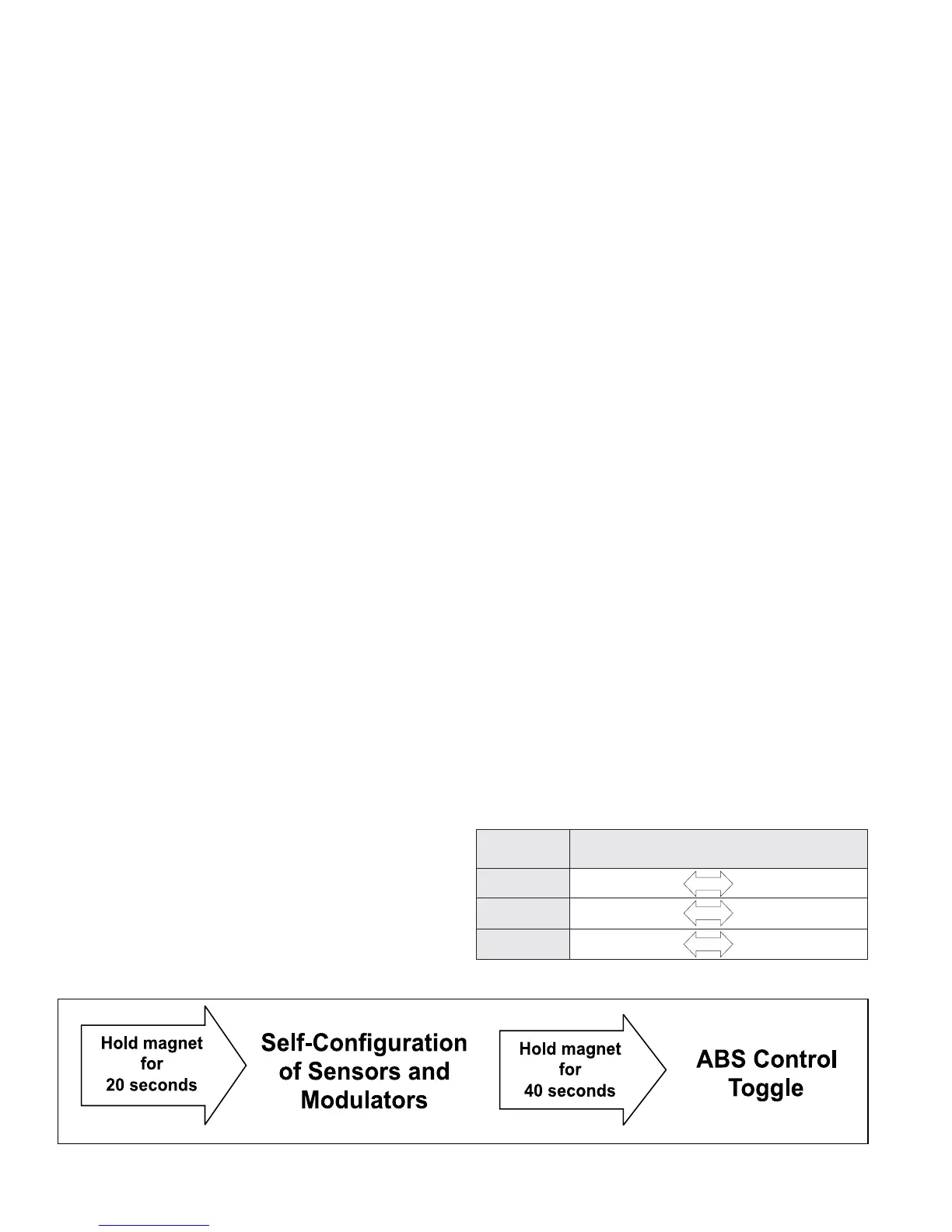
Hold a magnet on the reset location of the diagnostic
display. All of the LEDs will be on while the magnet is
held in place.
After holding the magnet in place for 20 seconds, the
LEDs will begin to roll and the MC-30
™
controller will self-
confi gure for the number of detected wheel speed sensors
and modulators. If it is not desired to toggle the ABS
control, remove the magnet.
The MC-30
™
controller will then automatically go through
the power-up sequence and display the new confi guration
on the diagnostic LEDs. Verify the new ABS confi guration
by monitoring the diagnostic LEDs at power-up or by
activating blink code diagnostics.
If an erroneous sensor or modulator combination is
detected during the self-confi guration, fault codes are
activated when the MC-30
™
controller returns to normal
operating mode.
ABS Control Toggle Procedure
To also toggle the ABS control, continue to hold the magnet
in place while the LEDs are rolling, for an additional 20
seconds (total of 40 seconds). After holding the magnet in
place for 40 seconds, the LEDs will begin to rapidly fl ash.
At this point the MC-30
™
controller will toggle the ABS
control confi guration. Remove the magnet.
The MC-30
™
controller will then automatically go through
the power-up sequence and display the new confi guration
on the diagnostic LEDs. Verify the new ABS confi guration
by monitoring the diagnostic LEDs at power-up or by
activating blink code diagnostics.
CHART 5 - SELF-CONFIGURATION AND ABS CONTROL TOGGLE ACTIVATION
CHART 6 - ABS CONFIGURATION AND CONTROL TOGGLE
ABS
Confi guration
Control Group A Control Group B
Tog gle
Toggle
Toggle