Note: Ultimate Tow is load activated and cannot be tested without load. At no load, the output reading of high voltage will register.
The output voltage is PULSED, so it cannot be measured with a voltmeter or test light.
INSTALLATION:
1. Disconnect the vehicle’s NEGATIVE battery terminal.
2. Determine a suitable mounting location inside the cabin.
3. Hold the brake controller in the selected position and
mark the hole location through the holes in the flanges
of the unit.
4. Using a suitable drill bit, drill holes in the marked locations.
5. Secure the brake controller in position with self-tapping
screws. Take care to not strip the holes by over-tightening
the screws or use the nylon fabric fastening hook and loop
straps, or double-sided adhesive pad to secure.
6. Drill a hole for the 8.5mm remote control shaft in a
suitably sized mounting panel in the dash with a wall
thickness of less than 4mm.
7. Affix decal, washer and retaining nut over shaft and
tighten. Turn shaft fully counter-clockwise and affix the dial
on the shaft with firm, even pressure with the indicator
facing the minimum position.
8. Plug the remote control lead into the brake controller.
9. Connect brake wiring as per wiring instructions and follow
Set-up and Operation procedures.
10. Reconnect the NEGATIVE battery terminal.
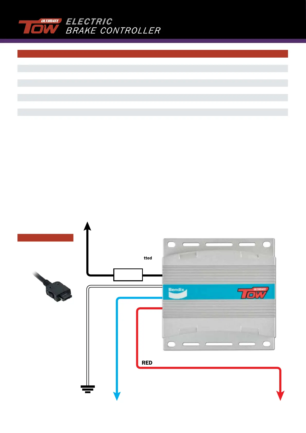
To Remote Control
To Positive Voltage Feed
(ie. Battery Positive)
To Vehicle Brake Switch (Cold Side)
or source that is pure DC when
vehicle brake lights are on.
Note: Only Activated by Positive feed.
To trailer brake wire /
Pin 5 on Trailer Plug
as described in
AS 4177.5-2004
Earth
BLACK
BLUE
WHITE
RED
Fuse must be fitted
(Supplied)
FUSE
WIRING DIAGRAM
Note: If you cannot attach to the vehicle brake switch. Follow the alternative wiring diagrams.
Specifications
Minimum Input Voltage 9 VDC
Nominal Input Voltage 12 VDC
Maximum Input Voltage 15 VDC
Suitable For 12V Trailer Brakes Yes
No Current Load 30 mA
Maximum Load 2 Axle /14A avg
Weight 200g
Dimensions L x W x H: 30mm x 57mm x 90mm
Model Fuse
ULTTOW12V 15A