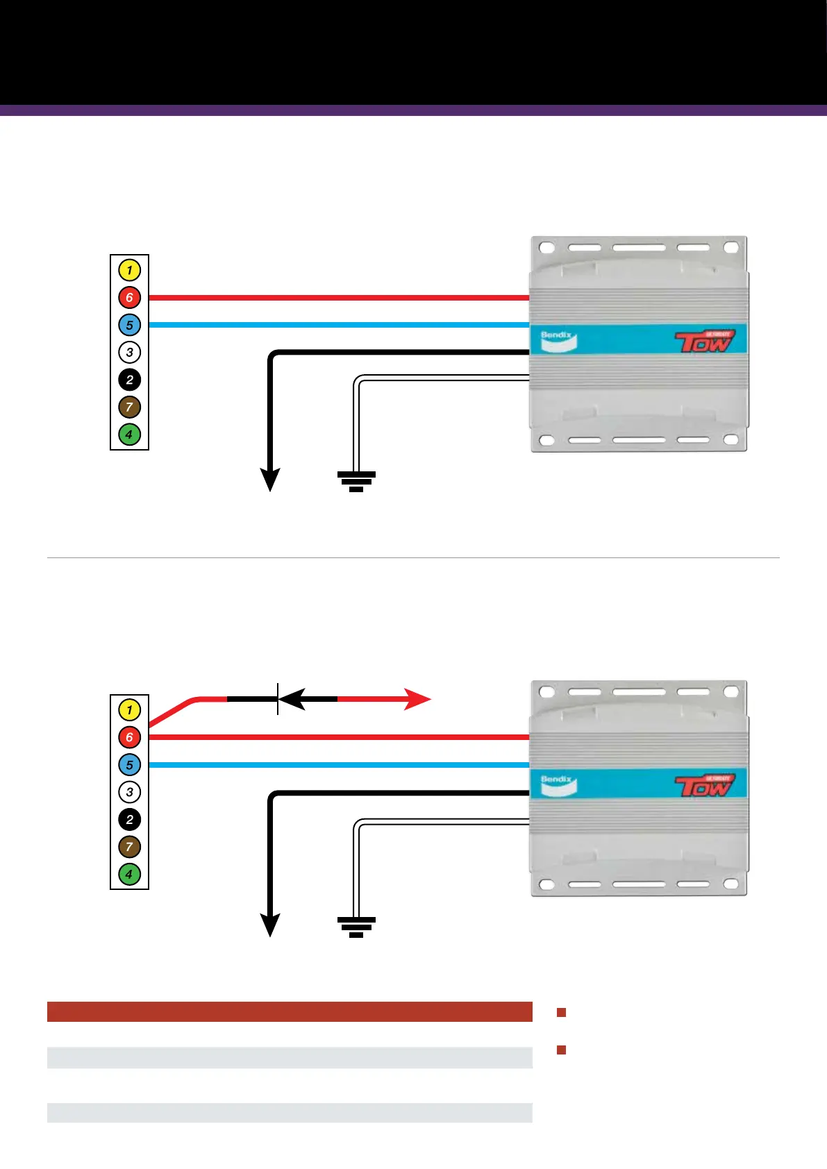
ALTERNATIVE WIRING DIAGRAM:
FOR CONNECTIONS IN VEHICLES WITH NO ASSISTED SAFETY SYSTEMS
ALTERNATIVE WIRING DIAGRAM:
FOR CONNECTIONS TO VEHICLES WITH ASSISTED SAFETY SYSTEMS
Please note: an external fuse
must be fitted (not supplied).
The control unit is activated by a
positive feed brake switch only.
(Please check the polarity of your
vehicles brake switch before
connection)
Note: Not all wiring shown. Do not alter wires that are not shown. Wiring must be connected as per AS 4177.5-2004.
Note: Not all wiring shown. Do not alter wires that are not shown. Wiring must be connected as per AS 4177.5-2004.
Wire Guide
White Wire Negative Battery
Blue Wire Brake
Black Wire Positive Battery
Fuse : 12V 20A / 24V 15A
Red Wire Brake Switch
7 Pin Trailer Socket
7 Pin Trailer Socket
Blocking Diode needs
to be fitted (supplied).
To vehicle wiring
12V Positive
12V Positive
Earth/Negative
Diode must be rated to at least 7A 12V
7 Pin Trailer Socket
Blocking Diode needs
to be fitted (supplied).
To vehicle wiring
12V Positive
Earth/Negative
Diode must be rated to at least 7A 12V
When computerized systems prevent attaching the red wire to the brake switch directly. Please follow the appropriate wiring diagram
below for your situation.