DASH LABEL MOUNTING INSTRUCTIONS:
PLEASE ENSURE THAT A FUSE IS FITTED ON THE BLACK WIRE (POSITIVE BATTERY)
(Optionally a 20A fuse may also be fitted to the BLUE brake wire)
The BLACK wire is the positive voltage power supply line. A
fuse must be fitted (refer to table above for size).
The RED wire must be connected to a point that receives
a DC Voltage equal to that of the supply voltage when the
brakes are on. Generally, for most vehicles we strongly
recommend that you connect the RED wire to the cold side
of the brake light switch. If this is not an option for your
vehicle, then any point that receives a straight DC voltage
should be applicable. For example- top rear tail light, brake
light relay or the wire connecting to the stop lights on the
trailer plug.
NOTE: Vehicles that use the same globe/supply for rear and
tail lights cannot have the RED wire to the stop light/tail
lights directly. Please use the alternatives listed above.
The BLUE brake wire must be connected directly to the
trailer brake wire.
The WHITE ground wire must be connected to a grounded
metal part of the dashboard, vehicle fire wall or directly to
the negative battery terminal.
Important: A brake control unit that is not properly grounded may operate intermittently or not at all.
Make sure all connections are secure.
Do not connect the Black “BATTERY” wire to the fuse panel or tie into any accessory wiring.
Connecting to the existing wiring may damage the vehicles wiring and cause trailer brake failure.
Do not reverse Black “BATTERY” wire and White “GROUND” connections.
Even a momentary incorrect connection can damage the brake control unit.
1. Refrain from using the vehicle chassis as a conduit for
the earth return for the brake coils. Facilitate a separate
ground wire. (See point 3 below)
2. Mount the brake controller and route all cables for
the input and output of the brake controller away from
antennas and RF Equipment.
In the unlikely event of RF Interference, you may wish to try one of the following :
The Remote Brake Controller has four (4) coloured wires- BLACK, RED, BLUE and WHITE.
3.
Use a short as possible bifilar (or twisted) wire to feed
the Ultimate Tow and brake coils ( both active and return).
4. Add a ferrite clamp over the RED, BLUE, BLACK
& WHITE wires.
7 Pin Trailer Socket
7 Pin Trailer Socket
Blocking Diode needs
to be fitted (supplied).
To vehicle wiring
12V Positive
12V Positive
Earth/Negative
Earth/Negative
Diode must be rated to at least 7A 12V
7 Pin Trailer Socket
7 Pin Trailer Socket
Blocking Diode needs
to be fitted (supplied).
To vehicle wiring
12V Positive
12V Positive
Earth/Negative
Earth/Negative
Diode must be rated to at least 7A 12V
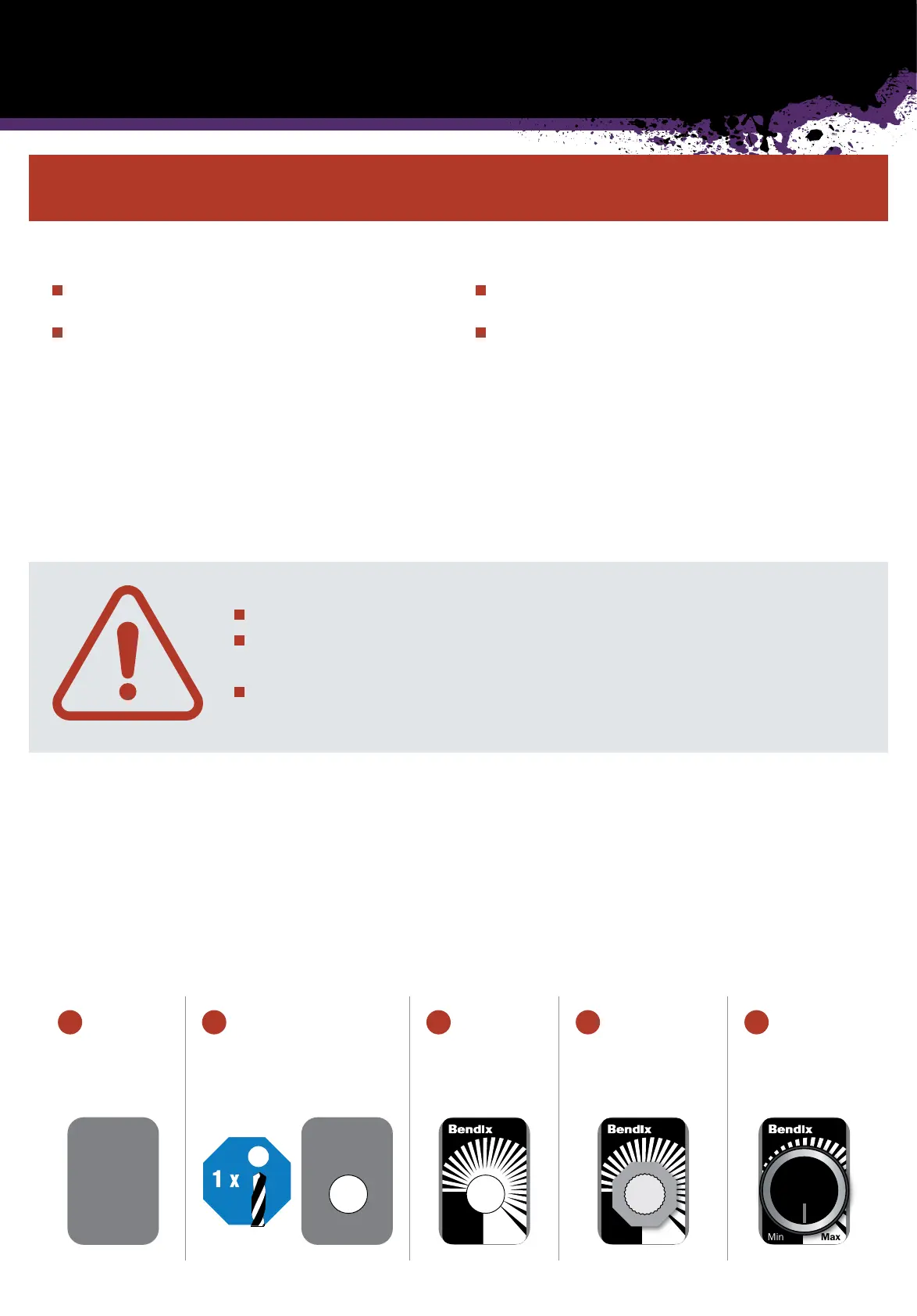
Installation on
standard blank
switch plate
Drill 1 × 8.5mm hole Apply dash sticker Insert shaft of dial and
fasten with supplied
nut until tight
Press on dial with
firm even pressure
1 2 3 4 5