be still available.
By manually opening the gate leaf, check that the
actuator does not hit the leaf or the pillar.
4) Only after this check, carry out the final welding of
the S bracket. The actuator should be perfectly flat.
Important: the respect of dimensions indicated in Fig. 3
ensures the optimal operation of the automatic system.
These different dimensions may cause malfunctions.
In any case, the manufacturer shall be held
unharmed with respect to damages caused by the
non-respect of the dimensions indicated.
If it is not possible to carry out welding, adjustable
brackets, which can be mounted by using screws (art
B.SR), are available as optional accessory.
Fix the actuator to the bracket by means of screws and
nuts supplied. Use washers as shown in Fig. 4.
Note: The difference between measures X and Y shall
be never exceed 40mm. Greater differences cause the
unsmooth movement of the gate.
Dimensions M and X should be carefully checked to
avert that the actuator hits the pillar (dim. M) or the
leaf (dim. Z).
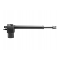
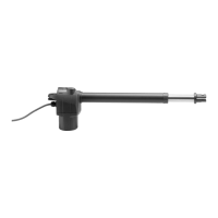
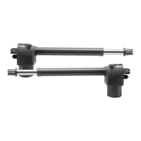
The total stroke of the actuator is around 520mm. The
stroke, however, cannot be entirely used. An extra
stroke of around 10 mm should be always provided
both in the closing and opening phases.
* In the BILL 50 geared motor, the difference in height
of brackets P and S shall be nil. These brackets should
be therefore fitted at the same height (Fig. 1, ref. A}
Wire connections
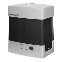
BILL 50 is supplied with a pre-cabled wire, around 80
cm long, to be connected to the junction box fitted to
the pillar.
BILL 50:
In the 230V model, the cable includes 4 terminals:
BLACK Gear 1
BROWN Gear 2
GREY Motor, common
Yellow/Green Earth
BILL 5024:
In the 24V model, the cable includes 2 terminals (BLUE/
BROWN)
Note:
The motor cable shall be replaced only by an authorised
assistance centre.
IT IS MANDATORY to connect the system to ground
by using the special GND terminal, as provided by
regulations in force.
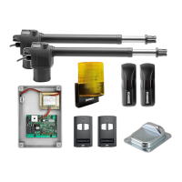
WARNING
The insurance policy, which covers any damages or
injuries caused by manufacture faults, requires that
the installation comply with regulations in force and
Benincà original accessories be used.
TECHNICAL DATA
BILL 50M BILL 50MA BILL 5024
Motor power supply
230Vac
50/60Hz
115 Vac
50/60Hz
24Vdc
Consumption 1,35 A 2,7 A 5 A
Max. thrust 3200 N 3200 N 2000 N
Operating jogging 30 % 30 % Heavy duty
Protection level IP54
Operating temperature -20°C / +50°C
Capacitor 10 μF 36 μF -
Useful stroke 500 mm
Noise <70 dB
Lubrication Permanent grease
Weight 7,1 kg 7,1 kg 5,5 kg
 Loading...