9
Introduction
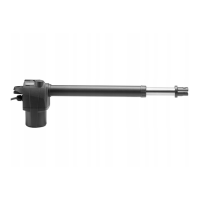
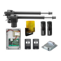
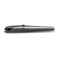
Electromechanical operator to activate swing gates,
available in the following models:
BILL50M: with motor powered at 230 VAC.
BILL50MA: with motor powered at 115 VAC.
BILL5024: with motor powered at 24 VDC.
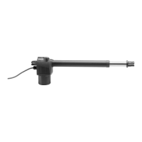
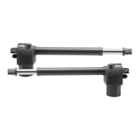
For 5very model, the RGHT (DX) version is also
available to install the system on the right gate leaf,
and the LFT (SX) version is available for installation on
the left gate leaf.
In case of doubt, as shown in the instruction manual,
the wording DX (right) or SX (left), which identifies the
different models, can be seen by opening the release
handle.
For simplicity reasons, this manual shows the SX
motor for left gate leaves. For the DX (right) versions,
installation dimensions and instructions are the
same.
The main dimensions are shown in Fig. 1.
t#FGPSFJOTUBMMJOHUIFTZTUFNSFBEUIFJOTUSVDUJPO
herein.
t*UJTNBOEBUPSZOPUUPVTFUIF#*--JUFNGPS
applications different from those indicated in the
instructions herein.
t4VQQMZUIFFOEVTFSXJUIJOTUSVDUJPOTGPSVTJOHUIJT
system.
t
The end user should receive special instruction manual.
t"MM#FOJODËJUFNTBSFDPWFSFECZBOJOTVSBODFQPMJDZ
for damages and injuries caused by manufacture
faults. It is however required that the machine
bear the CE marking and original Benincà parts be
used.
General information
To ensure a good operation of these automatic devices,
the gate to be automated should meet the following
requirements:
- good strength and stiffness.
- hinges should have a minimum backlash and allow
for smooth and regular manual operations.
- when closed, the gate leaves should correctly
overlap for their entire height.
Warning: BILL50 is not equipped with electric limit
switches or mechanical stoppers. It is mandatory that
the gate leaf be equipped with mechanical stoppers
fitted to the ground (Fig.2 ref. A and B).
Operating limits
The following tables show the permitted maximum
weight and width figures of the gate leaves.
BILL 50M / BILL 50MA
Max gate leaf weight (kg) 250 350 400 500 600 700
Max gate leaf (m) 5,0 4,5 4,0 3,5 3,0 2,5
BILL 5024
Max gate leaf weight (kg) 200 300 350 450 500 600
Max gate leaf (m) 5,0 4,5 4,0 3,5 3,0 2,5
IMPORTANT: For gate leaves wider than 4.00 mt,
an electric lock is required.
How to install the system
1) Define the height of the system from ground (the
most centred possible with respect to the main door
and corresponding to a rugged crossbeam).
2) Weld the P plate, taking account of figures X and Y
of Fig. 2/3.
3) Release the actuator, as shown in the instruction
manual. When the gate is closing, temporarily lock the
S* bracket by keeping the K measure as per Fig. 2/3. In
these conditions, the actuator must not be positioned
entirely at end of stroke, but 10mm extra-stroke should
The product shall not be used for purposes or in ways
other than those for which the product is intended for and
as described in this manual. Incorrect uses can damage
the product and cause injuries and damages.
The company shall not be deemed responsible for the
non-compliance with a good manufacture technique of
gates as well as for any deformation, which might occur
during use.
Keep this manual for further use.
Qualified personnel, in compliance with regulations in
force, shall install the system.
Packaging must be kept out of reach of children, as it can
be hazardous. For disposal, packaging must be divided
the various types of waste (e.g. carton board, polystyrene)
in compliance with regulations in force.
The installer must supply all information on the automatic,
manual and emergency operation of the automatic sy-
stem and supply the end user with instructions for use.
;
An omnipolar switch/section switch with remote
contact opening equal to, or higher than 3mm
must be provided on the power supply mains..
Make sure that before wiring an adequate differential
switch and an overcurrent protection is provided.
Pursuant to safety regulations in force, some types of in-
stallation require that the gate connection be earthed.
During installation, maintenance and repair, cut off power
supply before accessing to live parts.
Descriptions and figures in this manual are not binding.
While leaving the essential characteristics of the product
unchanged, the manufacturer reserves the right to modify
the same under the technical, design or commercial point
of view without necessarily update this manual.
WARNING
 Loading...