9
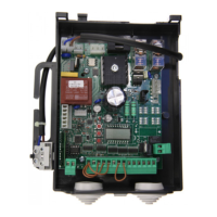
DA.24V/CP.EVA Control Unit
INPUT/OUTPUT FUNCTIONS
N° of terminals Function Description
1-2 Power supply Input, 230Vac 50/60Hz (1-Neutral/2-Phase)
4-5 Motor 24Vdc Connection to motor, 24Vdc
6-7 Flasher Flasher connection, 24Vac 40W max.
8-9 24 Vac
Output, accessories power supply - 24Vac/0.5A max.
IMPORTANT: If the battery charger board CB.24V is installed,
the output (without mains power connected) has a 24Vdc po-
larised voltage. Make sure the devices are correctly connected
(i.e. 8:+24Vdc - 9:-24Vdc).
10-11 Road barrier lights
Connection of barrier beam lights, 24Vdc (10+/11+) -200mA
max (equal to approx. 6 lights).
12 COM Common to all control inputs.
13 STOP Input, STOP push-button (N.C. contact)
14 PHOT
Input, safety devices connection, N.C. contact
(ex. Photocells)
15 OPEN Input, OPEN push-button (N.O. contact)
16 CLOSE Input, CLOSE push-button (N.O. contact)
17 Step-by-Step Input, step-by-step push-button (N.O. contact)
18 COM Common, limit switches.
19 SWC
Input, CLOSURE limit switch (N.C. contact).
When this contact is opened, power supply to the motor is cut-
off at the end of the road barrier closing operation.
TECHNICAL DATA
Contol unit supply
24 Vdc
Power supply
230 Vac 50/60 Hz
Output supply
1 motor 24Vdc
Power maximum motor
120 W
Output supply accessories
24Vdc 500mA max.
Protection level
IP54
Operating temp.
-20°C / +50°C
Radio receiver
Removable connector for radio receiver