11
DIP 5 “LIGHT” The operating mode of the road barrier lights connected to terminals 10/11 is
selected.
Off: Slow flashing with open or closed road barrier.
Fast flashing during operation.
On: Fixed light on, with up or moving road barrier. Light off with barrier down,
controlled by the triggering to the SWC-R limit switch.
DIP 6 “COND.” The multi-flat function is enabled or disabled.
Off: disabled multi-flat function.
On: enabled multi-flat function. The P.P. (Step-by-step) impulse or the impulse
of the transmitter have no effect in the opening phase and during TCA phase (if
activated).
DIP 7 “AMPCL” The amperometric sensor is enabled or disabled during braking in the closing
phase.
Off: Enabled amperometric sensor during braking in the closing phase
On: Disabled amperometric sensor during braking in the closing phase..
DIP 8 “Trall-OP” The amperometric sensor is activated or deactivated during braking in the opening
phase.
Off: 2 sec braking with inactivated amperometric sensor.
On: 2 sec braking with activated amperometric sensor. If the amperometric
sensor is activated during the 2s braking, the road barrier stops immediately its
movement.
If required, the system can be controlled in SERVICE MAN mode by switching all Dip Switched to ON
TO ADJUST THE ROAD BARRIER SPEED
WARNING! This adjustment affects the safety level of the automatic system.
Check that the force applied to the road barrier beam complies with regulations in force.
Any change in speed requires a new calibration of the amperometric sensor.
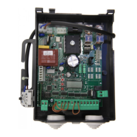
A Faston (VMOT) connector is provided on the power supply transformer. This allows for the adjustment of
the road barrier motor speed at three different levels (18-23-26).
By positioning the Faston (VMOT) to 18 a lesser speed is provided, by moving the Faston to 26 a higher
speed is provided.
Should the VE.AM mobile stand or the VE.RAST rack be present, reduce the beam speed.
DIAGNOSTICS OF LEDS
The control unit is provided with a series of self-diagnostic LEDs which permit to check all functions:
POWER LED It flashes to indicate the presence of mains power supply
STOP LED It switches off when the STOP button is activated
PHOT LED It switches off when the photocells are not aligned or in the presence of obstacles
OPN LED It switches on when the OPEN button is activated
CLS LED It switches on when the CLOSE button is activated
PP LED It switches on when the PP button is activated
SWC LED It switches off when the SWC closing limit switch is activated
SWO-R LED It switches off when the SWO-R opening braking limit switch is activated
SWC-R LED It switches off when the SWC-R closing braking limit switch is activated
WASTE DISPOSAL
If the product must be dismantled, it must be disposed according to regulations in force regarding the
differentiated waste disposal and the recycling of components (metals, plastics, electric cables, etc..). For
this operation it is advisable to call your installer or a specialised company.