6
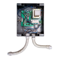
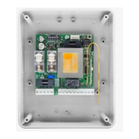
DA.93AM Control unit with microcontroller
The control unit ”DA.93AM” can be used with motors having a total power not exceeding 750W.
Installation instructions.
a) The electric installation and the operating logic must comply with regulations in for
ce.
b) It is advisable to keep the power cables (motor, power supply) detached from the control cables (push-but-
tons, photocells, radio). In order to avert any possible interference it is recommended to provide for and use
two separate sheaths (see EN 60204-1 15.1.3).
c) Before powering the unit, check again all connections which have been carried out.
d) Check that the presettings of the Dip-Switches are correct.
e) When the unit is powered, the LED “POWER” must be lit; in the negative, check that fuses are in
good condition and that 230Vac 50Hz power supply is present between terminals 1 and 2 (INPUT 230VAC
- keep to line/ground connection).
f) The N.C. inputs not used must be connected to the common “+V”.
Input/Output functions
Terminal No. Function Description
(1,2) INPUT 230VAC Control unit 230Vac 50 Hz power supply (respect phase/neutral wire
position).
(3,4,5) COM/ APRE/
CHIUDE M1
Connection to the corresponding 230Vac 50 Hz motor terminals (delayed
in closing) (the earth wire (green/yellow) must be connected).
(6,7,8) COM/ APRE/
CHIUDE M2
Connection to the corresponding 230Vac 50 Hz motor terminals (delayed
in opening) (the earth wire (green/yellow) must be connected).
(9,10) LAMP230 Connection to the 230Vac blinker.
(11,12) CORTESIA Connection to the 230Vac courtesy lamp.
(13,14) OUT 24VAC 24Vac auxiliary power supply output (1Amax.).
(15,16) ELS 12Vac output for electric lock.
(17,18) SCA 24Vdc ”Gate open warning light” contact (250mA).
Function for the ”Gate open warning light” contact.
•If the gate is closed, the warning light is turned off.
•If the gate is opening, the warning light ashes slow (about 1Hz).
•If the gate is closing, the warning light ashes fast (about 2Hz).
•If the gate is open, or the race is interrupted manually (PP - STOP), the
warning light remains turned on.
N.B.: The led is driven by a relay, thus the commutation can be normally
heard during the normal function of the control board.
(19,20) +V Common connection to all the control inputs.
(21) FTCA Opening photocell receiver input (n.c. contact) (photocell far from the
gate).
(22) FTCC Closing photocell receiver input (n.c. contact) (photocell near the gate).
(23) FCA1 Limit switch input - M1 motor opening (n.c. contact).
(24) FCA2 Limit switch input - M2 motor opening (n.c. contact) - opening delay.
(25) FCC Limit switch input - M1 and M2 motor closing (n.c. contact).
(26) STOP STOP button input (n.c. contact).
(27) PED PEDESTRIAN button input (n.o. contact).
(28) P.P. STEP-by-STEP button input (n.o. contact).
(29) APRE OPEN button input (n.o. contact).
(30) CHIUDE CLOSE button input (n.o. contact).
(31,32) ANT. Input of radio board antenna
(33,34) RX 2CH. Radio board 2nd channel contact (n.o. contact).
J1 RTX Connector for receiver board of the remote control
JP1 SPUNTO Selection jumper, “PICKUP” of starting motors
1) Closed : enabled pickup
2) Open : inhibited pickup
The power of motors can be controlled through the 5-step commutator “MOTOR POWER”.
 Loading...