Do you have a question about the Beninca DREAMY and is the answer not in the manual?
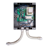
Safety warnings regarding wire connections, voltage separation, and checking settings before powering.
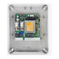
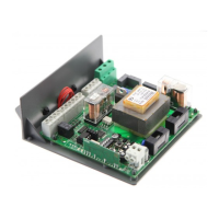
Details on terminal functions for power supply, motor, auxiliary outputs, and control inputs.
Specifies DREAMY input voltage (230VAC or 115VAC) and connection details.
Instructions for connecting the motor (3-move/4-Com/5-move) and capacitor.
Description of the auxiliary output (N.O. contact, 230Vac, 5Amax).
Details on the 24VAC output for accessories (100 mA max).
Functions of COM, Step-by-Step/Open, STOP/Close, and PHOT inputs.
Connection for antenna and description of the incorporated bi-channel radio receiver.
Explanation of the DL1 diagnostic LED status indications.
Information on protection fuses for motor, light, and 24VAC output.
Step-by-step guide to verify correct wiring and motor operation.
Detailed explanation of each DIP-switch function for receiver mode, inputs, and outputs.
Procedure to learn motor stroke operating time and automatic closure time (TCA).
Description of the special 'Service Man' mode and its limitations.
Instructions for configuring the radio receiver for different transmitter types.
Procedure to store a new transmitter code for Step-by-Step operation.
Procedure to store a new transmitter code for the 2nd radio channel.
Procedure to store a new transmitter code for the Pedestrian function.
Instructions to erase all previously stored transmitter codes from memory.
Procedure for learning new transmitters without direct access to the control unit.
| Brand | Beninca |
|---|---|
| Model | DREAMY |
| Category | Control Unit |
| Language | English |