6
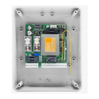
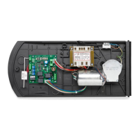
DREAMY Control Unit
The DREAMY control unit can be used to control 1 motor with power not exceeding 1500W.
GENERAL WARNINGS
a) The wire connections and the operating logic should be in compliance with regulations in force.
b) The cables featuring different voltage should be physically separated, or adequately insulated by an
additional insulation of at least 1 mm.
c) The cables should be further fastened in proximity to the terminals.
d) Check all connections before powering the unit.
e) Check that setting of the Dip-Switches are the required ones.
f) Normally Closed inputs which are not in use should be short-circuited.
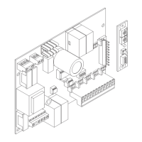
INPUT/OUTPUT FUNCTIONS
Terminals Function Description
1-2 Power supply
DREAMY: Input, 230VAC 50/60 Hz (L-Phase/N-Neutral)
DREAMY 115: Input, 115VAC 50/60 Hz (L-Phase/N-Neutral)
3-4-5 Motor Connection to motor (3-move/4-Com/5-move)
3-5 Capacitor
Connection to motor capacitor.
Do not use for motors equipped with built-in capacitor.
6-7 AUX
Auxiliary output (N.O. contact – 230Vac (5Amax.), configurable through
Dip-Switch 4.
8-9 24 VAC Output, power supply of accessories, 24VAC/100 mA max
10 COM Common, for control inputs.
11
Step-by-Step
(Open)
Input, Step-by-step or OPEN push-button, configurable through Dip-
Switch 3.
12
STOP
(Close)
Input, STOP push-button (N.C. contact) or CLOSE push-button (N.O.
contact), configurable through Dip-Switch 3.
13 PHOT
Input, photocell active in the opening and/or closing phase (Normally
Closed, voltage-free contact).
See Dip-Switch 5.
14-15 Antenna
Connection of the antenna to the incorporated radio-receiver module
(14-signal/15-display).
MD1 RADIO
Incorporated, bi-channel radio receiver for variable code, ARC (Advanced
Rolling-Code) code or fixed code transmitters, 433.92 MHz.
See Dip-Switch 1 and “Configuration of incorporated receiver”.
DL1 LED
Diagnostics LED. Slow flashing indicates mains power supply. Fast flashc-
ing is used for the learning of the stroke and the remote control program-
ming.
FUSES
F1 Protection fuse, motor and flashing light
F2 Protection fuse, 24VAC output
HOW TO CHECK CONNECTIONS:
1) Turn power off.
2) Manually release the door and push it for about half stoke. Lock the door again.
3) Turn power on.
4) Send a step-by-step or radio-control signal.
5) The door must move in the opening phase. In the negative, with motor stopped, invert the wires (3/5) of
the motor.
 Loading...