7
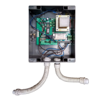
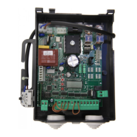
HEAD Control Unit
The electronic control unit HEAD can be used to control 2 motors with a power not exceeding 350+350W.
GENERAL WARNINGS
a) The wire connections and the operating logic should be in compliance with regulations in force.
b) The cables featuring different voltage should be physically detached, or adequately insulated by an additional
insulation of at least 1 mm.
c) The cables should be further fastened in proximity to the terminals.
d) Check all connections before powering the unit.
e) Check that settings of the Dip-switches are the required ones.
f) The N.C. inputs which are not in use should be short-circuited.
INPUT/OUTPUT FUNCTIONS
Terminal No. Function Description
1-2 Power supply Input, 230Vac 50Hz (1-Phase/2-Neutral)
3-4 Flashing light Output, ashing light connection, 230Vac 40W max.
5-6-7 Motor 2 Connection to motor 2 : (5-move/6-Com/7-move)
8-9-10 Motor 1 Connection to motor 1 : (8-move/9-Com/10-move) – delayed in closing
phase. If only one motor is used, connect Motor 1 output and adjust
TRAC to the minimum value.
11-12 24 Vac Output, accessories power supply 24Vac/1A max.
13-14 Electric lock Electric lock connection, 12Vac/0,5A max.
11-15 SCA Open gate indicator light connection, 24 Vac/3W max.
16-17 RX 2ch. Output, second radio channel. N.O. contact, voltage free.
It is enabled with both xed receiver and expandable two-channel re-
ceiver
18-19 Aerial Aerial connection, radio receiver card and incorporated radio module
(18-screen/19-signal).
20 Pedestrian Input, N.O. pedestrian push-button
Activation is carried out on motor M1 (8-9-10)
21 Step-by-Step Input, N.O. step-by-step push-button
22 STOP Input, N.C. STOP push-button
23 PHOT Input, safety devices connection, N.C. terminal (e.g. photocells)
24 +V Common to all control inputs.
25-26-27 0-24-12 Connection to transformer secondary winding
28-29-30 L1-T1-N1 Connection to transformer primary winding
J3 Radio receiver Connector for two-channel radio receiver (optional)
To check connections:
1) Cut-off power supply.
2) Manually release the wings, move them to approx. half-stroke and lock them again.
3) Reset power supply.
4) Send a step-by-step control signal by pressing the button or the remote control key.
5) The wings should start an opening movement. If this is not the case, invert the movement wires of the motor.
(8/10 for motor M1, and 5/7 for motor M2).
6) Adjust Time, Operating Logic and Motor Power.
To adjust the motor power
WARNING! This adjustment affects the safety of the automatic system.
Check that the thrust applied onto the wing complies with regulations in force.
A Faston (T1) connector is provided on the power supply transformer which allows the power adjustment of the
motors on 4 different levels. By moving the Faston (T1) to 120, power is at minimum, by moving it to 230, power
is at maximum.
Position 230 can be used only with motors complete with adjustable mechanical clutch.