28
3) Unlock the motor (Fig. 11) and bring the overhead door to the opening position and cut the two straight arm components as shown
in Fig. 10. Slide square tube T onto arm B and secure the latter to plate P using the screws supplied.
Balance the door by increasing the existing counterweights or spring tensioning so that the unlocked overhead door remains STILL at
approx. 45° (approx. half stroke). Test the balancing at various points of the stroke.
Thread the square tube MARK.T180 onto the arm MARK.D and secure it to the plate P with the screws provided.
5) If necessary, rebalance the door by increasing the counterweights so that the unlatched overhead door remains STILL at approxi-
mately 45°.
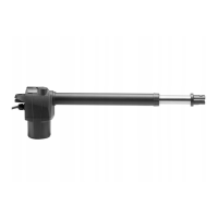
NOTE: In the case of lateral installation of two MARK geared motors, all of the above indications apply, with the difference that in this case
it is possible to use the MARK.DT telescopic arm, which has already pre-welded a 220 mm square tube, to be shortened if necessary.
10) OPENING LIMIT SWITCH ADJUSTMENT
The opening limit switch is supplied, to adjust to set the stoppage point in desired opening proceed as follows:
• Unlock the door to move it manually (Fig. 15)
• Loosen the screw G locking the cam C (Fig. 11-A)
• Bring the door manually to the desired opening position.
• Adjust the cam for intervention of the micro-switch M (Fig. 11-B)
• Fasten the screw G (Fig. 11-C)
• Close the door
11) WIRING - FIG.16
Fig.16 outlines the wiring to prepare for complete installation of the accessories with the two motors (1 MARK+1MARK.SC).
Before proceeding with passage of the cables, check the type of cabling required for the accessories actually used.
KEY
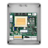
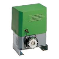
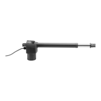
A MARK gearmotor with CP.MARK control panel incorporated
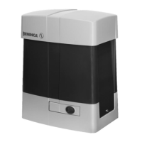
B MARK.SC gearmotor
C Pair of photocells
D Flashing light with integrated antenna
E Key selector or digital keypad
F Mains power supply
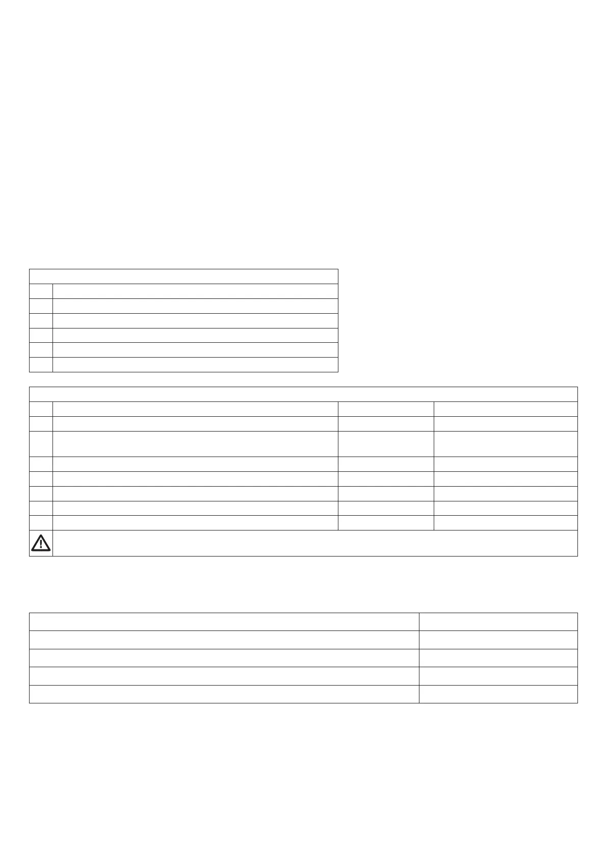
List of cables
Connection Type Maximum length
1 MARK mains power supply 3x1,5mm
2
30m
B MARK.SC motor connection:
2x1,5mm
2
3x0,5mm
2,
Motor 24V 10 m max
Encoder 10m max
C Photocell transmitter connectio 2x0,5mm
2
20m
D Photocell receiver connection 4x0,5mm
2
20m
E Key selector connection for external command 4x0,5mm
2
20m
F Signalling flashing light connection 2x1,0mm
2
10m
G Integrated antenna connection in flashing light RG 58
The cables used must be suitable for the type of connection. For example for connections protected by a duct use
H03VV-F type cables, for the cables in an external environment use type H07RN-F.
The MARK motor is equipped with a control panel, to which the MARK.SC, gearmotor, the accessories (flashing light, photocells, etc.)
and the control devices (buttons, key selector, etc.) are connected.
Pass the adequately channelled cables through the cable glands prepared.
For connection of the MARK.SC motor to the control panel, the section of the cable must meet the values indicated below:
Distance between the MARK.SC motor and CP.MARK control panel Wire type
Up to 5m 2x1,5mm
2
from 5 m to 7.5 m 2x2,5mm
2
from 7.5 to 10m 2x4mm
2
Over 10m Not recommended
 Loading...