29
EN
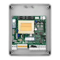
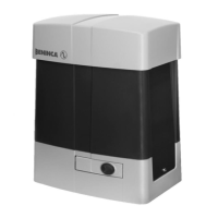
12) CP.MARK CONTROL PANEL
ELECTRICAL CONNECTIONS
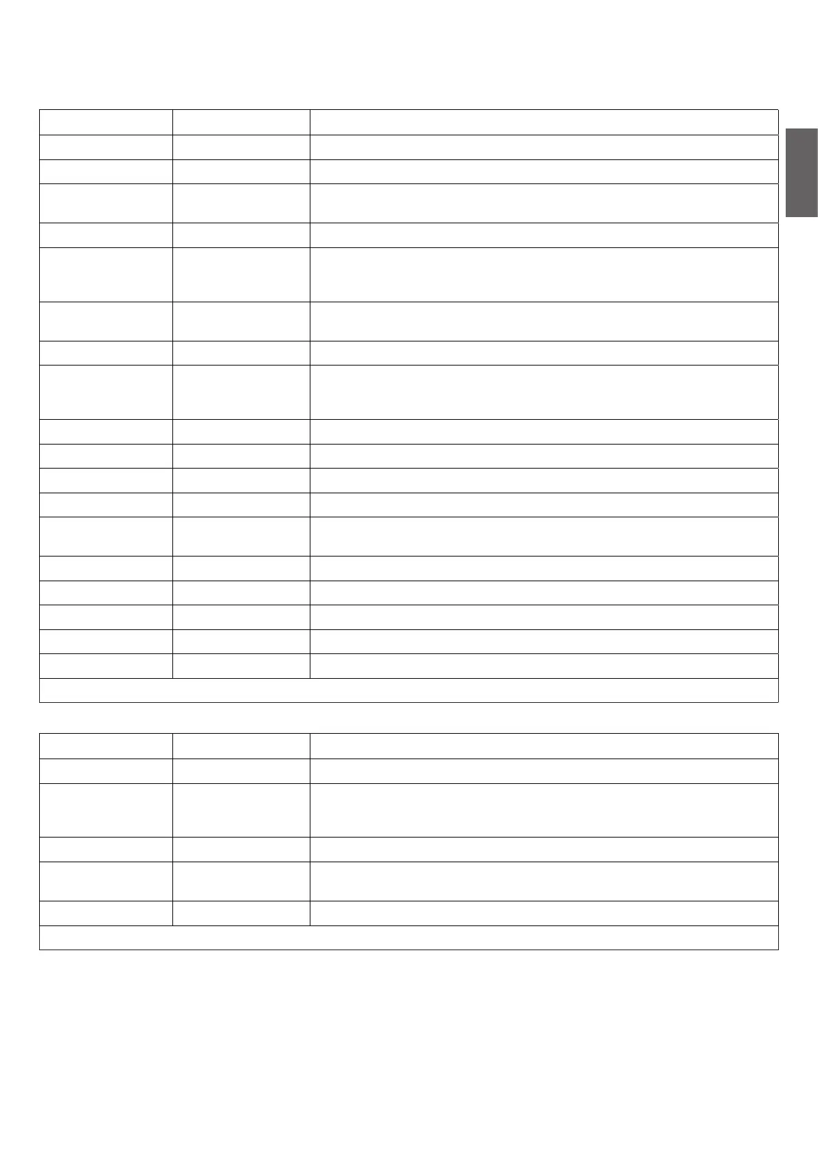
The following table shows the electrical connections in Fig. 17:
Terminals FUNCTION DESCRIPTION
L-N-GND Supply Input 230Vac 50 Hz (L-Phase/N-Neutral-GND)
+ BATT - Back-up Battery Connection for back-up battery connection (no. 2 batt.12V Mod.)
POWER SUPPLY
(EL.S)
Electric lock Exit the power supply of the electric lock control board art. L.BY (optional).
MOT 1 (M1) Motor 1 Quick connector for Motor 1 24Vdc*
MOT 2 (M2) Motor 2
Connector for Motor 2 24Vdc.
Use for possible second motor MARK.SC or if two motors MARK.SC with side
assembly with separate control panel.
+24- Power supply
SERV. L
Courtesy light M2
Exit for power supply of courtesy light Motor 2 (to connect to a possible second
motor MARK.SC)
ENC Encoder Quick connector for connection of motor encoder *
COM-SWO-SWC Limit switch
Quick connector for the connection of the limit switch*. As standard, the opening
limit switch is supplied (SWO). The closure limit switch (SWC) is available as an
accessory.
ANT-SHIELD Antenna Antenna connection (SHIELD-screen/ANT-signal).
COM COM Common for all control inputs.
P.P. Step-by-Step Step-by-Step button input (N.O. contact)
AUX IN 1 AUX 1 input Input configurable via IN 1 parameter
PHOT/BAR
Photocell or
Sensitive edge
Safety device connection input, N.C. contact. (photocell) or 8K2 for sensitive
edge.
STOP STOP STOP key input (N.C. contact)
AUX IN 2 AUX 2 input Input configurable via IN 2 parameter
BLINK (BLK) Flashing Flashing connection 24Vdc 4W max.
-24+ Power supply 24Vdc Exit for accessories power supply 24Dc max 0.5A
AUX AUX N.O. contact voltage free, configurable from parameter AUX 1.
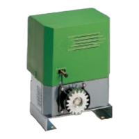
* Pre-wired connection in the event of MARK gearmotor with control panel incorporated.
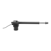
In the MARK.SC version (without control unit) there is a board present for connection and the LED MARK.L lights.
Terminals FUNCTION DESCRIPTION
MOT Motor Quick connector for Motor 24Vdc**
COM-SWO-SWC Limit switch
Quick connector for connection of the limit switch**. It is supplied as standard
with an opening limit switch (SWO). The closure limit switch (SWC) is available as
an accessory.
MOT Motor Connect to output MOT2 of the control panel CP.MARK
POWER SUPPLY
SERV. L
Courtesy light Connect to output SER.L of the control panel CP.MARK
COM-SWO-SWC Limit switch Quick connector for the connection of the limit switch*
** Pre-wired connection.
TYPES OF INSTALLATION
Three types of installation are planned:
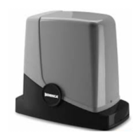
1) A motor MARK with incorporated control panel for central installation (Fig. 18). For doors with standard dimensions
2) Two side motors, a MARK with incorporated control panel and a MARK.SC (Fig. 18). For larger doors or with a pedestrian entrance
door.
3) Two side motors MARK.SC and control panel installed on wall MARK.SC (Fig. 18). For larger doors or with a pedestrian entrance door
and you present the control panel on wall.
IMPORTANT: If two motors are used, use the limit switch of a single motor.
 Loading...