33
EN
TST3
It enables or disables the PHOT/BAR input TEST.
Activation of the TEST function is only possible using items SC.RF and RF/RF.SUN, consult
the specific instructions.
On: Check enabled. If the check has a negative outcome, no manoeuvre is commanded.
See Fig.5 - “BAR TEST”.
Off: Test disabled.
(OFF)
PHCL
Selection of the PHOT input operating mode.
On: Input used as the Photocell Input enabled in OPENING and CLOSING.
Off: Input used as the Photocell Input enabled in CLOSING.
(OFF)
BAR
Selection of the PHOT/BAR input operating mode.
On: Input used as the Sensitive Edge Input 8K2
Off: Input used as the Photocell Input as operation set by PHCL
(OFF)
AOPF
Enables or disables the “Forced opening function without mains) function (can only be
enabled with the emergency batteries connected and working).
On: Function enabled. In the event of a power cut, the control panel forces an opening
manoeuvre. The door remains open until the mains power supply is restored.
Off: Function not enabled.
(OFF)
CUar
Enables or disables the cloned ARC transmitters.
On: The AK series transmitters closed from an ARC transmitter already stored are enabled.
Off: The cloned transmitters are not enabled.
(ON)
REM
Enables or disables remote switching of radio transmitters (see REMOTE LEARNING sec-
tion).
On: Remote entry enabled
Off: Remote entry disabled
(ON)
esa
Enables or disables the ESA energy saving function.
With the ESA function enabled once opening or closing movements have been completed,
the control panel is in maximum energy efficiency condition, reducing absorption to mini-
mum and disconnecting accessory outputs.
On: ESA energy saving function enabled (default).
Off: ESA energy saving function disabled.
To use if you want to have the accessories power supply output always enabled, for exam-
ple if using 24 Vdc keypads or other devices that need to be always powered
(ON)
RADIO (RADi)
MENU FUNCTION
PP
Selecting this function, the receiver sets in standby (Push) of a transmitter code to assign to the step-step function.
Press the transmitter key you intend to assign to this function.
If the code is valid, it is saved and the message OK is displayed
If the code is not valid, the message Err is displayed
2Ch
Selecting this function, the receiver sets in standby (Push) of a transmitter code to assign to the second radio channel.
Press the transmitter key you intend to assign to this function.
If the code is valid, it is saved and the message OK is displayed
If the code is not valid, the message Err is displayed
sair
Selecting this function, the receiver sets in standby (push) of a transmitter code to assign to the SIAR function (Partial
opening set by the SAIR parameter).
Press the transmitter key you intend to assign to this function.
If the code is valid, it is saved and the message OK is displayed
If the code is not valid, the message Err is displayed
LSTM
Selecting this function, the receiver sets in standby (push) of a transmitter code to assign to the Courtesy light function,
whose operation is set by the TLS parameter.
Press the transmitter key you intend to assign to this function.
If the code is valid, it is saved and the message OK is displayed
If the code is not valid, the message Err is displayed
n tx
Selecting this function, the LCD display shows the number of transmitters saved in the receiver.
CLR
Selecting this function, the receiver sets in standby (Push) of a transmitter code to delete from the memory.
If the code is valid, it is cancelled and the message OK is displayed
If the code is not valid or there is no memory, the message Err is displayed
RTR
Completely deletes the receiver memory. Confirmation is required of the operation.
By selecting this function, the receiver sets in standby (Push) of a new PGM press to confirm the operation.
At the end of the deletion, the message OK is displayed.
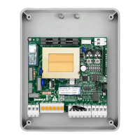
Note: The transmitters are saved on an EPROM memory (Fig.1 -U11) which can be removed and reinserted in a new control panel in
the event of replacement.
 Loading...