8
SC.RF
DESCRIPTION
Two-channel radio receiver, with 868 MHz frequency, pursuant
to the regulation EN 12978, to be matched to radio transmitters
of the RF/RF SUN series for movable clsoures.
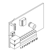
OVERALL DIMENSIONS
The overall dimensions of the radio-receiver box are shown in
Figure 1. A bi-adhesive strip is supplied to apply the box inside
the automation system or the control system.
WIRE CONNECTIONS (Fig. 4)
CH1* Output, channel 1 replies the status of the sensitive sa-
fety edge memorised on channel 1 – normally closed
contact.
CH2* Output, channel 2 replies the status of the sensitive sa-
fety edge memorised on channel 2 – normally closed
contact.
12/24 Input, 12 or 24 VAC or VDC power supply. It can be
selected through a 12/24 jumper. In case of 12/24 VDC
power supply, keep to poles shown in Figure 2.
ANT Input, antenna. For a better reception, it might be ne-
cessary to remove the pre-installed cable and use a
868MHz antenna.
TST TEST input, see AUTOTEST paragraph.
* CH1 and CH2 outputs are mainly connected to inputs for the
sensitive edge of the control unit. In this case, inputs should be
preset as if they were connected to a safety edge of the me-
chanical type.
The inputs for sensitive safety edges usually provide that, in the
event they are activated, the system is immediately stopped and
the movement is reversed for some seconds.
As an alternative, should no inputs be provided for sensitive
safety edges, channels CH1/CH2 can be connected to other
safety inputs, namely inputs for photocells or inputs for STOP
control signals.
If two channels must be connected to one single input in the
control system, the two outputs should be connected in series.
JUMPER
SC.RF is equipped with 4 jumpers for the following pre-set-
tings:
BZ: The acoustic signal is enabled or disabled.
Closed jumper: activated sound indicator
Open jumper: not activated buzzer
12/24: Power voltage is selected.
Closed jumper: 12 VAC/DC
Open jumper: 24 VAC/VDC
W1: The AUTOTEST (self-testing) function on channel 1* is ac-
tivated or deactivated
Closed jumper: AUTOTEST OFF
Open jumper: AUTOTEST ON
W2: The AUTOTEST (self-testing) function on channel 2* is ac-
tivated or deactivated
Closed jumper: AUTOTEST OFF
Open jumper: AUTOTEST ON
See AUTOTEST paragraph
HOW TO STORE THE RADIO TRANSMITTER IN MEMORY
In order to be able to communicate with the RF/RF.SUN radio-
transmitter, the transmitter code must be memorised and assi-
gned to either channels available.
8
SC.RF
DESCRIPTION
Two-channel radio receiver, with 868 MHz frequency, pursuant
to the regulation EN 12978, to be matched to radio transmitters
of the RF/RF SUN series for movable clsoures.
OVERALL DIMENSIONS
The overall dimensions of the radio-receiver box are shown in
Figure 1. A bi-adhesive strip is supplied to apply the box inside
the automation system or the control system.
WIRE CONNECTIONS (Fig. 4)
CH1* Output, channel 1 replies the status of the sensitive sa-
fety edge memorised on channel 1 – normally closed
contact.
CH2* Output, channel 2 replies the status of the sensitive sa-
fety edge memorised on channel 2 – normally closed
contact.
12/24 Input, 12 or 24 VAC or VDC power supply. It can be
selected through a 12/24 jumper. In case of 12/24 VDC
power supply, keep to poles shown in Figure 2.
ANT Input, antenna. For a better reception, it might be ne-
cessary to remove the pre-installed cable and use a
868MHz antenna.
TST TEST input, see AUTOTEST paragraph.
* CH1 and CH2 outputs are mainly connected to inputs for the
sensitive edge of the control unit. In this case, inputs should be
preset as if they were connected to a safety edge of the me-
chanical type.
The inputs for sensitive safety edges usually provide that, in the
event they are activated, the system is immediately stopped and
the movement is reversed for some seconds.
As an alternative, should no inputs be provided for sensitive
safety edges, channels CH1/CH2 can be connected to other
safety inputs, namely inputs for photocells or inputs for STOP
control signals.
If two channels must be connected to one single input in the
control system, the two outputs should be connected in series.
JUMPER
SC.RF is equipped with 4 jumpers for the following pre-set-
tings:
BZ: The acoustic signal is enabled or disabled.
Closed jumper: activated sound indicator
Open jumper: not activated buzzer
12/24: Power voltage is selected.
Closed jumper: 12 VAC/DC
Open jumper: 24 VAC/VDC
W1: The AUTOTEST (self-testing) function on channel 1* is ac-
tivated or deactivated
Closed jumper: AUTOTEST OFF
Open jumper: AUTOTEST ON
W2: The AUTOTEST (self-testing) function on channel 2* is ac-
tivated or deactivated
Closed jumper: AUTOTEST OFF
Open jumper: AUTOTEST ON
See AUTOTEST paragraph
HOW TO STORE THE RADIO TRANSMITTER IN MEMORY
In order to be able to communicate with the RF/RF.SUN radio-
transmitter, the transmitter code must be memorised and assi-
gned to either channels available.
 Loading...