24
7) ARC COMPATIBLE CONTROL UNIT
IMPORTANT, PLEASE READ CAREFULLY:
The radio receiver in this product is compatible with the new ARC (Advanced Rolling Code) transmitters which, thanks to 128-bit encryption
ensure superior copy-security.
Storing new ARC transmitters is quite similar to that of normal rolling code transmitters with HCS coding, but be aware that:
1) ARC transmitters and Rolling Code HCS can not be stored in a single receiver.
2) The first transmitter memorized determines the type of transmitters to be used later. If the first transmitter memorized is ARC, you
can not store Rolling code HCS transmitters, and vice versa.
3) Fixed code transmitters may only be used in conjunction with Rolling code HCS transmitters, bringing the logic CVAR OFF. They
are, therefore, not usable in combination with the ARC transmitters. If the first rolling code transmitter stored is an ARC CVAR the logic
is inoperative.
4) If you want to change the type of transmitters it is necessary to proceed with a receiver reset.
8) CONNECTION TO GROUND (EARTH)
As regards the COMPULSORY earthing, a special Faston 4-pin connector fitted onto the central support (Fig. 11 – GND) is supplied. Ground connections
of the mains, the upper removable side and the lower side can be connected to this Faston.
To allow an easy removal of the sides, they are not supplied pre-cabled to the connector. The installer shall provide for their connection, by using the
already equipped with Faston terminal.
As regards the ground connection of the power supply line refer to instructions in the control unit.
9) WIRE DIAGRAM
Figure 13 shows the cables to the preset for the installation of the gear motor and the main accessories.
As regards the wire connection of the automatic system and the adjustment of the operating modes, see the instruction manual of the control unit.
Namely, the calibration of the anti-crash device sensitivity (encoder) should be carried out in compliance with regulations in force.
Before introducing the cables, check the type of cabling required for the accessories actually used.
Key of components:
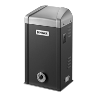
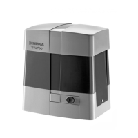
1 Gear motor with CP.BISON OM built-in control unit.
2 Rack
3 Limit switch brackets
4 Photocells
5 Mechanical stoppers
6 Key selector or digital keypad
7 Flashing light
8 Antenna
10) CP.BISON OM CONTROL UNIT
10.1) INPUT/OUTPUT FUNCTIONS
Terminal No. Function Description
1-2 Power supply Input, 230Vac 50Hz (1-Phase/2-Neutral)
3 GND
Ground connection. Use the connector preset on the fitting plate of the control unit.
Earthing is COMPULSORY, through this connection also the metal structure of motorization are
grounded.
4-5 Aerial Connection of the insertable radio receiver card (4-signal/5-display).
8-9 24Vac Output, power supply of accessories, 24VAC/1A max
10-11
SCA o
Service light
Normally Open clean contact, configurable as SCA (open gate light), timed service light (see SERL Logic)
or as second radio channel (see Logics 2 Ch).
12-13 PHOTO TEST
N.O. free contact. It is used to power photocell transmitters in TEST operating mode.
See diagram Fig.3 and TST1 and TST2 Logic.
14 COM Common for control inputs.
15 OPEN
Input, push-button for OPEN contact (Normally Open contact) Contact usable for timed openings through
timer.
16 CLOSE Input, CLOSE push-button (N.O. contact)
17 Step-by-Step Input, step-by-step push-button (N.O. contact)
18 PED
Input, pedestrian push-button (N.O. contact). It controls the partial opening. Configuration is through
parameter TPED. When TCA time has elapsed (if activated) a closure control signal is sent.
19 COM Common, for limit switches and safety devices
20 STOP Input, STOP push-button (N.C. contact)
21 PHOT O
Input, (N.C. contact) for safety devices (e.g. photocells).
In the closing phase: the contact opening causes the motor stop. Common: when the photocell is re-
leased, the motor inverts the movement direction (open).
In the opening phase: the contact opening causes the motor stop. When the photocell is released, the
motor re-starts the opening operation.
22 SWO Input, OPEN limit switch (N.C. contact)
23 SWC Input, CLOSE limit switch (N.C. contact)
 Loading...