12/ 2007
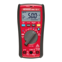
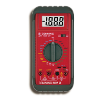
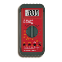
BENNING MM P3
24
40 V 10 mV ± (0.9 % of the measured value + 5 digits) 600 V
eff
400 V 100 mV ± (0.9 % of the measured value + 5 digits) 600 V
eff
600 V 1 V ± (1.5 % of the measured value + 5 digits) 600 V
eff
The measured value of the BENNING MM P3 is obtained by mean value rectication
and is displayed as r.m.s. value.
*1
The measuring accuracy is specied for a sinusoidal curve. In case of non
sinusoidal curves, the accuracy of the displayed value decreases.
7.3 Resistance measuring range (Switch setting: Ω, ,
)
Overload protection for resistance measurements: 600 V
eff
Measuring range Resolution Measuring accuracy
Max. open-circuit
voltage
400 Ω 0.1 Ω ± (0.9 % of the measured value + 5 digits) 0.4 V
4 kΩ 1 Ω ± (0.9 % of the measured value + 2 digits) 0.4 V
40 kΩ 10 Ω ± (0.9 % of the measured value + 2 digits) 0.4 V
400 kΩ 100 Ω ± (0.9 % of the measured value + 2 digits) 0.4 V
4 MΩ 1 kΩ ± (1.5 % of the measured value + 5 digits) 0.4 V
40 MΩ 10 kΩ ± (1.5 % of the measured value + 5 digits) 0.4 V
7.4 Diode and continuity test (Switch setting: Ω, ,
)
Overload protection: 600 V
eff
The integrated buzzer sounds at a resistance R lower than 50 Ω.
Measuring range Resolution
Max. measuring current
Max. opencircuit voltage
1 mV 1.1 mA 1.5 V
7.5 Capacity ranges (Switch setting:
)
Conditions: Discharge capacitors and apply them according to the specied polarity.
Overload protection for capacity measurements: 600 V
eff
Measuring range Resolution Measuring accuracy
50 nF 10 pF ± (5.0 % of the measured value + 0.2 nF)*
500 nF 100 pF ± (2.9 % of the measured value + 5 digits)
5 µF 1 nF ± (2.9 % of the measured value + 5 digits)
50 µF 10 nF ± (2.9 % of the measured value + 5 digits)
100 µF 100 nF ± (2.9 % of the measured value + 5 digits)
The measuring duration depends on the capacitor size and might take up to 20 seconds.
* The measuring accuracy is specified for measured values from 10 nF and for pre-
vious null balance by means of the „RANGE/ REL Δ ( )“ key 6