BenQ G700 Service Manual
30
dimming frequency is determined by the external resistor R507 and capacitor C516 connected to pin11 of
IC501. C511 is used for soft start and compensation, C507, C518 are used for dump noise.
The output drives, include DRV1, DRV2 (pins1,15 respectively) output square pulses to drive
MOSFET U501, U502, and each of U501, U502 , is consist of a N channel MOSFET. U501,OR U502
work as Push-Pull- topology, it is high efficient, PWM switching.
During start up, VSEN (pin6) senses the voltage at the transformer secondary. When VSEN reaches 3.0V,
the output voltage is regulated. If no current is sensed approximately 2seconds IC501 shut off.
The current flowing through CCFL is sensed and regulated through sense resistor R509, R534. The feedback
voltage connected to Pin5 (ISEN), then compared with a reference voltage (1.5V) via a current amplifier,
resulting in PWM drive outputs to PUSH-PULL switches
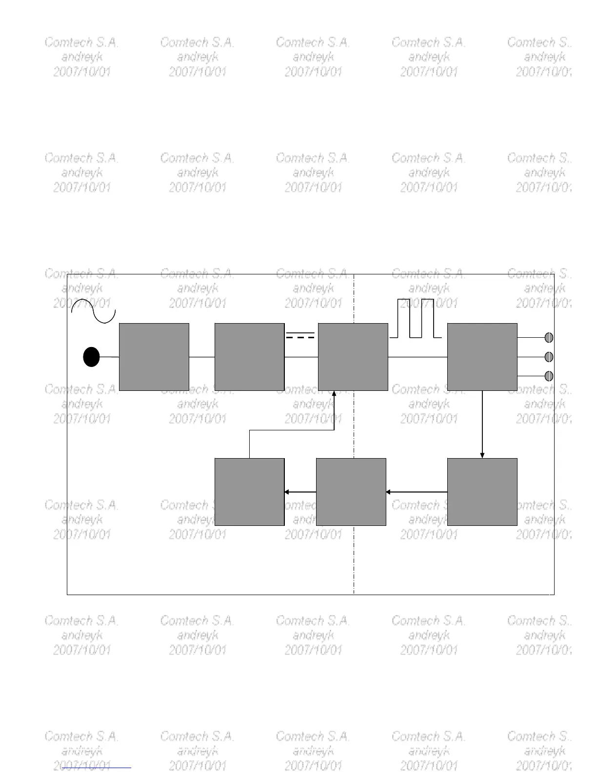
5.2.2 Power board diagram:
EMI
COMPONENTS
INPUT REXTIFIER
AND FILTER
ENERGY
TRANSFER
OUTPUT RECTIFIER
AND FILTER
SIGNAL
COLLENTION
PHOTO-COUPLER
ISOLATION
PWM
COMTROL
CIRCUIT
LINE
100~240V
12V
5V
GND
SECONDARY
PRIMARY
66KHzHVDC
EMI
COMPONENTS
INPUT REXTIFIER
AND FILTER
ENERGY
TRANSFER
OUTPUT RECTIFIER
AND FILTER
SIGNAL
COLLENTION
PHOTO-COUPLER
ISOLATION
PWM
COMTROL
CIRCUIT
LINE
100~240V
12V
5V
GND
SECONDARY
PRIMARY
66KHzHVDC

 Loading...