Chapter 5 Technical Information
5.4 Signal connector pin assignment
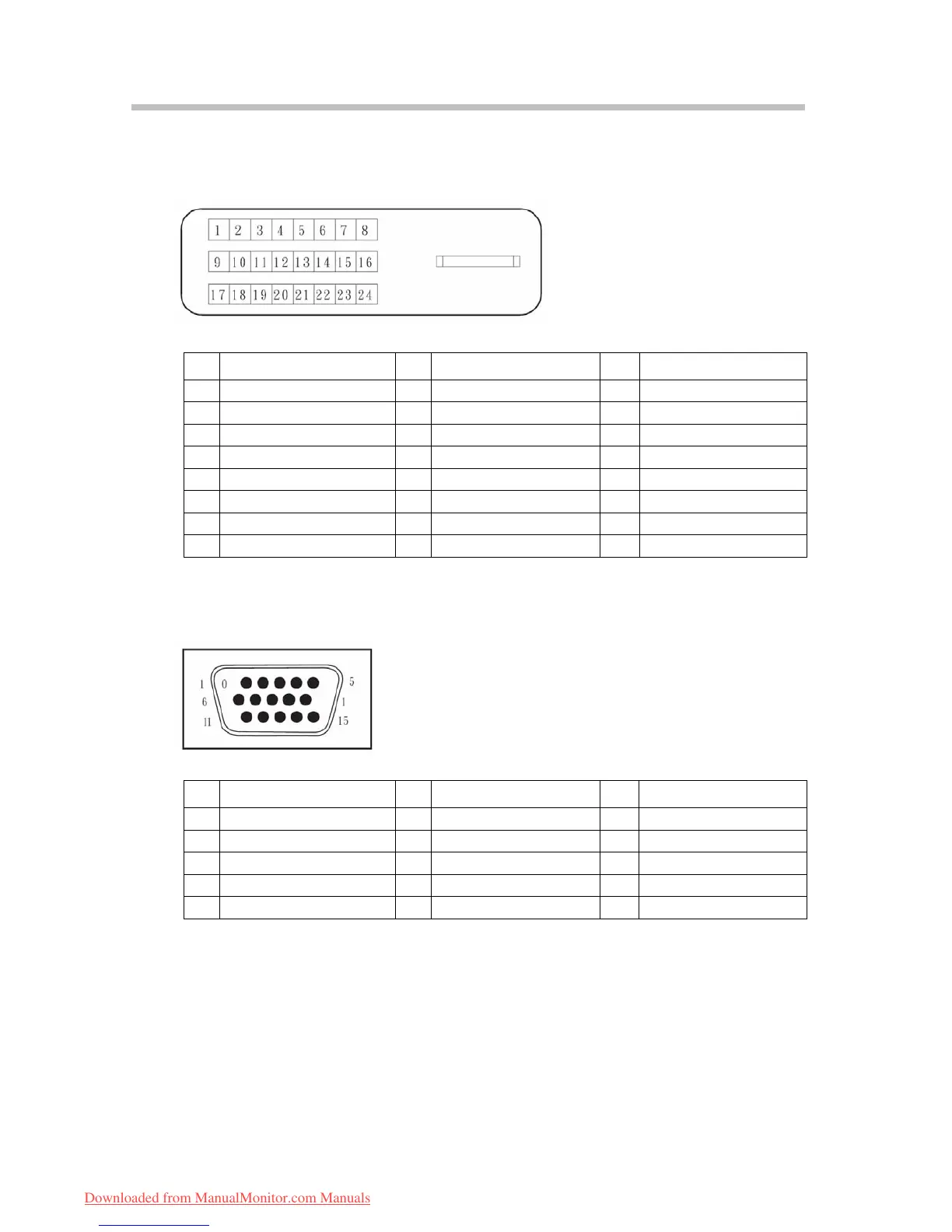
5.4.1 DVI-D signal connector pin assignment
The PIN assignment of the DVI-D connector / cable is as following:
PIN Signal PIN Signal PIN Signal
1
TMDS Data 2-
9 TMDS Data 1- 17 TMDS Data 0-
TMDS Data 2+
2 10 TMDS Data 1+ 18 TMDS Data 0+
3
TMDS Data 2/4 shield
11
TMDS Data 1/3 shield
19 TMDS Data 0/5 shield
4
TMDS Data 4- (open)
12 TMDS Data 3- (open) 20 TMDS Data 5- (open)
5
TMDS Data 4+ (open)
13 TMDS Data 3+ (open) 21
TMDS Data 5+ (open)
6
DDC Clock
14
+5V Power
22 Clock shield
7
DDC Data
15 GND 23 Clock+
8
Analog Vertical Sync
16 Hot Plug Detect 24 Clock-
5.4.2 D-Sub signal connector pin assignment
The PIN assignment of the mini D-SUB connector / cable is as following:
PIN Signal PIN Signal PIN Signal
1 Red 6 Ground Red 11 Ground (open)
2 Green 7 Ground Green 12 SDA (DDC Data)
3 Blue 8 Ground Blue 13 H – Sync
4 Ground (open) 9 +5 V for DDC 14 V – Sync
5 No Pin (ground) 10 Ground 15 SCL (DDC Clock)
13
Downloaded from ManualMonitor.com Manuals
 Loading...