Doc No. 20-45-159 Page 3 of 60
Introduction.
W
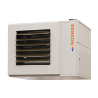
elcome to the Gas Fired Cabinet Heater Range.
Local regulations may vary in the country of use and it is
the installers responsibility to ensure that such regulations are
satised
All installation, assembly, commissioning and service
procedures must be carried out by suitable qualied
competent persons to the statutory regulations in the
country of use.
When installing, commissioning and servicing is undertaken
on these heaters due care and attention is required to
ensure that working at height regulations are adhered to at the
mounting heights specied.
All Dimensions shown are in mm unless
PLEASE READ this document prior to installation and
use. The safety of this heater is guaranteed only by the
correct usage in accordance with these instructions, therefore
it is recommended that they are retained for future reference.
The manufacturer reserves the right to alter specications without
prior notice.
Document Index.
1 Installation requirements
1.1 Compliance notices
1.2 Certicates of conformity
1.3 General product information
1.4 General requirements
1.5 Delivery and pre-installation checks
1.6 Warranty
1.7 Health and Safety
1.8 Location / Positioning
1.9 Gas supply
1.10 Electrical supply - general
1.11 Air supply
1.11.1 Heaters installed within the heated space.
1.11.1.1 Natural ventilation openings to the
heated space.
1.11.2. Heaters Installed within a plant room or
enclosure.
1.11.2.1 Natural ventilation openings to plant
rooms
1.11.2.2 Natural ventilation openings to
enclosures
1.11.2.3 Mech ventilation - plant room or
enclosure.
1.12 Air distribution system
1.13 Flue system.
1.14 Dimensions
1.15 Technical details
1.15.1 Reference information
1.15.2 Technical information
2 Installation Instructions
2.1 Packaging/siting
2.2 Flooring
2.3 Minimum clearances
2.4 Assembly
2.5 Flue installation
2.6 Gas Installation/Connection
2.7 Electrical Installation/Connection
2.8 Air distribution installation
2.9 Warm air registers
2.10 Heater control installation
Wiring diagrams
3 Commissioning instructions
3.1 Commissioning - pretest
3.2 Commissioning - ignition
3.3 Commissioning - air delivery system.
3.4 Commissioning - hand over
4 Servicing instructions
4.1 Planned servicing.
4.2 Servicing procedure - Major component parts
4.2.1 Flue
4.2.2 Main fan motor
4.2.3 Main fan
4.2.4 Pulleys
4.2.5 Fan belts
4.2.6 Heat exchanger
4.2.7 Electrical supply
4.2.8 Gas supply
4.2.9 Burner
4.2.10 Air delivery system
4.2.11 Report
4.3 Service re-commissioning
5 Spare parts
6 Fault nding guide
7 Replacing parts
7.1 Burner
7.2 Controller
7.3 Electrode assembly
7.4 Contactor/Overload
7.5 MCB
7.6 Fan/Limit stat assembly
7.7 Fan belts
7.8 Blower motor
7.9 Fan blower
8 User and Operating Instructions
8.1 Commissioning and hand over
8.2 Servicing
8.3 Start up procedure
8.4 Stop procedure
8.5 Shut down procedure
8.6 Ventilation only
8.7 Lockout situations