Drain
Valve
Fuel
Tank
lilled
to facilitate drainage
Vent
Pipe
Isolating
Air
Nozzles
Fusible
a--+--c::l"'---t
Link
Fire
Burner
Filler
Valve
Valve
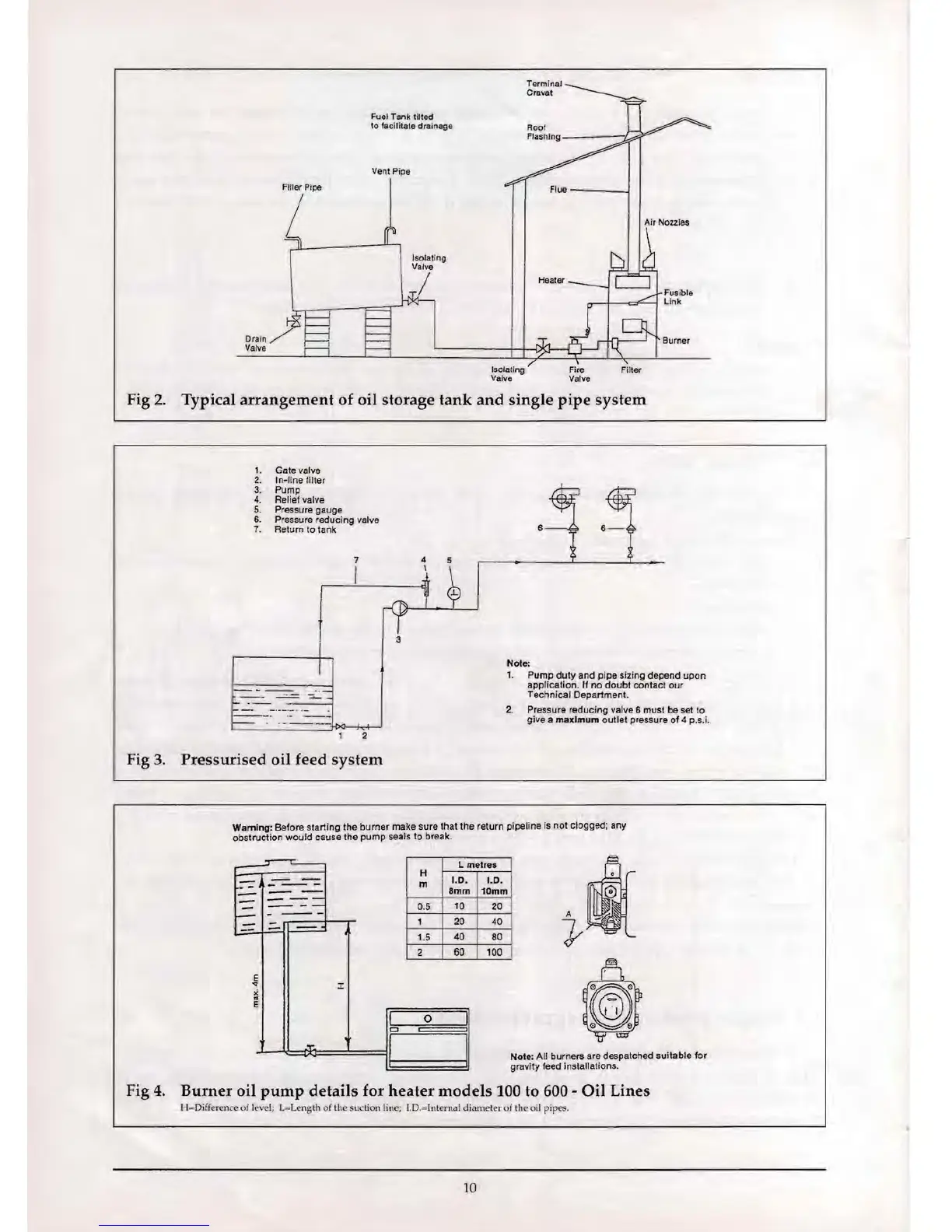
Fig
2.
Typical
arrangement
of
oil storage
tank
and
single
pipe
system
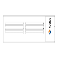
1.
Gate valve
2.
In-line tilter
3. Pump
4.
Reliet valve
5.
Pressure gauge
6. Pressure reducing valve
7.
Return to tank
7
I
.- --
--
I
Note:
1. Pump duty and pipe sizing depend upon
application.
If
no
doubt contact our
Technical Department.
2. Pressure reducing
vatve
6 must be set to
give a maximum outlet pressure
of
4 p
.s.
i.
2
Fig
3.
Pressurised
oil feed
system
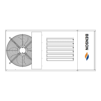
Warning: Before starting the burner make sure that the return pipeline
Is
not clogged; any
obstruction would cause the pump seals to break.
0
A '
..
I[
t -
.,'.
Y
n
::~:
y"ifD"
Nole: All burners are despatched suitable
for
gravity feed installations.
Fig
4.
Burner
oil
pump
details
for
heater
models
100 to 600 -
Oil
Lines
H=D
iff
erence
of
level; L=Length of
th
e suction line; I.D
.=
Intemal diameter of
th
e oil pi
pes.
~
L melres
H
-
--
m
1.0. 1.0.
--
---
-
Bmm
10mm
- I
.=--==
-=:.
1
----
0.5
10
20
-
--
I
-
1
20
40
--
-
-=-'
1.5
40
80
2
60
100
E
'"
J:
>i
'"
E
I
0
I
0
I i
~"I:.
10