3.0 Installation
It is strongly
advised
that
the
installer reads Section 2
and
Section 3 of this
manual
prior
to
starting
any
installation work.
It
is a requirement that only qualified
and
competent
personnel
may
undertake
instal1ation, commissioning,
and
servicing.
Warning
Always
ensure
that
the
appropriate
personal
protective
equipment
is
used.
3.1 Packaging/siting
The heater will usually be
supplied
wrapped
in heavy
gauge
polythene, non-assembled
parts
will be
supplied
separately. Prior to installation, the assembly of
the
heater
should
be completed, it
is advisable that this is
undertaken
in
the
area
where
the
heater is scheduled to be sited.
Caution
It
is
strongly
advised
that
when
positioning
the
heater
the
lifting
eyes
are
used,
thereby
reducing the risk of
inadvertent
damage
being
occasioned to the heater.
Prior to installation the heater
must
be
correctly positioned before
any
final assembly
work
is
completed. The
bonnet
top
and
outlet nozzles
must
be securely
attached
before installation can
commence.
3.2 Flooring
The
heater
must
be
installed
on
a level
non
combustible
surface
capable
of
supporting
the
weight of the heater
and
any
ancillary equipment.
3.3
Minimum
clearances
The following
minimum
clearances (in metres)
must
be observed
when
installing the heater.
'
Model
top
lhs
rhs
front
back
AH
100 - 600
AH
700 -1000
0.9
2.0
0.9
0.9
0.9
0.9
0.5
2.0
1.35
2.0
[
3.4
Assembly
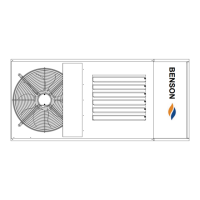
The following sub-assembly
parts
should
be assembled to allow installation to continue.
Place Nozzle Base plate
onto
the top
of
the heater, align holes,
and
secure. Fit the nozzles to the
spigots,
turning
the nozzles to give the required
approximate
direction for air flow. Adjust louvres
to
give
the
desired
angle
of
warm
air
down
flow.
Secure
nozzles
to
spigots,
when
correctly
positioned,
by
means
of drilling
and
inserting self
tapping
screws.
19