Option B
22
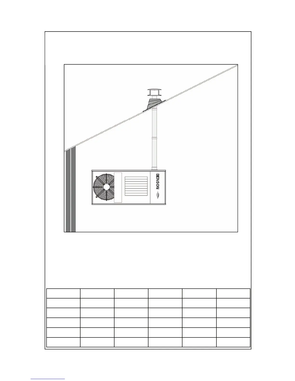
In this configuration the heater is connected to a single flue pipe to discharge the products
of combustion outside the building either through the roof or through a wall. The air for
combustion is taken from inside the building.
L1 maximum flue length 10 metres
Universal Terminal
Extra pipes to extend the flue are available as an option
Pipe Ø 130 x 1000 mm
Pipe Ø 130 x 500 mm
Pipe Ø 130 x 250 mm
Bend
Ø 130 x 45
0
Bend Ø 130 x 90
0
Part No
33-54-207
33-54-201
33-54-202
33-54-203
33-54-204
33-54-205
Heater Unit Flue Exit HORIZONTAL Flue Exit VERTICAL
MIN. MAX. MIN. MAX.
250 m 1,00 8,00 1,00 10,00
330 m 1,00 8,00 1,00 10,00
410 m 1,00 8,00 1,00 10,00
490 m 1,00 8,00 1,00 10,00