7
!
"#$
%&'
#
#
(
"#
#
)#
*#
!
*##
(
INSTALLAZIONE
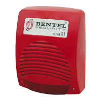
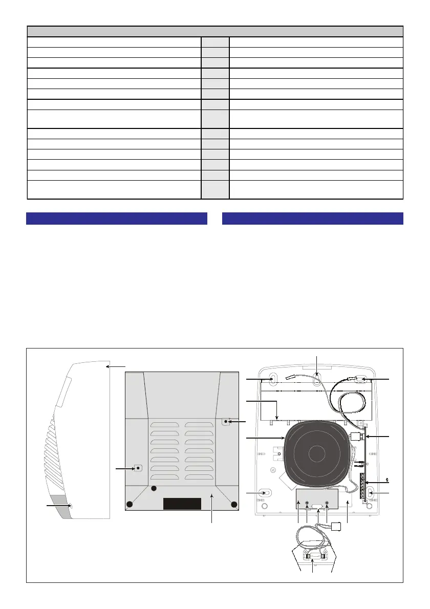
La sirena Call -R24 va fissata ad una parete che non
presenti avvallamenti e/o sporgenze eccessive.
Per facilitare l’operazione di installazione, nella con-
fezione troverete una dima per la foratura e viti per il
fissaggio. Sulla dima sono disegnati 5 fori : F1, F2,
F3, F4, F5, corrispondenti a quelli di fissaggio posti
sul fondo della sirena. Quest’ultima andrà fissata ai
punti 5 (fig. 3).
Per il passaggio dei cavi provenienti dalla centrale
utilizzate esclusivamente il foro 13. Fissata la sirena
potrete effettuare i collegamenti sulla morsettiera 9 e
Fig. 3 - Parti della sirena - siren pats
INSTALLATION
The CALL-R24 must be mounted on a flat sur-
face.
Drill the holes for wall mounting (use the drilling
pattern).
F1, F2, F3, F4, F5 on the drilling pattern corre-
spond to the wall mounting holes 5 on the
backplate.
Pull the control panel cables through the cable
passage PC (13) (see fig. 3).
Make the connections on the terminal board 9.
Install the battery on the support 6 and connect