n
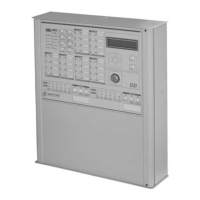
Connecting a Repeater
Connect the 24V, –, + and M terminals to the respecti
-
ve terminals on the Main Board of the Control panel, as
shown in Figure 17.
+
The maximum wire length connected the RS485
terminals of the Control panel must not exceed
1000 metres.
Connect the - terminal of the Repeater to the Main
Earth wire.
32 Conventional Fire Panels J424/J408
24V
RS485
24V
RS485
24V
RS485
24V
RS485
24V
RS485
Main board
Repeater panelRepeater panelRepeater panelRepeater panel
Connect
to the earth
conductor
Figure 17 Wiring diagram of a Repeater connection
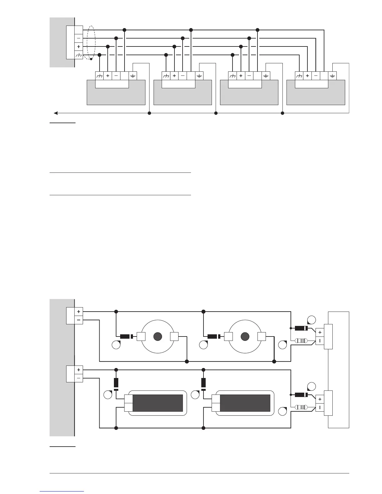
–+ –+
NAC1
FIRE
ALARM
–
+
FIRE
ALARM
–
+
HORN
STROBE
NAC2
Outdoor hornstrobe
Main board
114 114
114
Fire bel l Fire bell
Warning lamp
114
114 114
Warning lamp
109
109
Figure 18 Wiring diagram of Signalling devices: 109) 3900 ohm, 1/4 W EOL Resistor (orange-white-red-gold);
114) 1N4007 Diode or similar
 Loading...