4. Go back to step 1 to program another Output option
or, press the Next phase key 9 to go to the follo
-
wing Programming Phase (see Column A).
The “PANEL” Programming Phase
The PANEL LED will blink to indicate that the system is
ready to program the User Code, Day and Night Mode
Times and current Time and Date. During this phase,
the keys and LEDs will operate in accordance with the
options preceded by in the panes on the Program
-
ming Overlay, see Figure 32.
1. Using the keys in columns C and D, select the para
-
meter you want to program (refer to the respective
paragraph for details) or, press the Next phase
key 9 to go to the following Programming Phase
(see Column A).
n
User Code (Key/LED 1)
The LED will go On to indicate that the system is ready
to start the programming procedure.
Using keys 0 through 9, type in a 4 digit User Code. The
LED will go Off after entry of the fourth digit (indicating
that the “User Code” has been accepted).
n
Day Mode (Key/LED 2)
The LED will go On to indicate that the system is ready
to start the programming procedure.
Using keys 0 through 9, type in the “Time” when the
changeover from Night to Day Mode must occur.
Enter two digits for the Hour (00 to 23 — 00 for Mid
-
night) and two for the Minutes (00 to 59). The LED will
go Off after entry of the fourth digit (indicating that the
setting has been accepted).
n
Night Mode (Key/LED 4)
The LED will go On to indicate that the system is ready to
start the programming procedure.
Using keys 0 through 9, type in the “Time” (formatted as
per Day Mode) when the changeover from Day to Night
Mode must occur. The LED will go Off after entry of the fo
-
urth digit (indicating that the setting has been accepted).
n
Clock (Key/LED 5)
The LED will go On to indicate that the system is ready
to start the programming procedure.
Using keys 0 through 9, type in the current “Time” (for
-
mat as per Day Mode).
n
Date (Key/LED 7)
The LED will go On to indicate that the system is ready
to start the programming procedure.
Using keys 0 through 9, enter the respective two digits
for the Day (00 to 31), Month (00 to 12) and Year (00 to
99). The LED will go Off after entry of the last digit (indi
-
cating that the setting has been accepted).
Wrong entries will be signalled by an audible error si
-
gnal.
n
Mains Off Delay (Key/LED 8)
The LED will go On to indicate that the system is ready
to start the programming procedure.
Using keys 0 through 9, type in the length of time the
Control panel must wait before signalling a Mains Failu
-
re event.
Enter four digits (0000 through 9999 minutes). The LED
will go Off after entry of the last digit (indicating that the
“Mains Off Delay” has been accepted).
Wrong entries will be signalled by an audible error si
-
gnal.
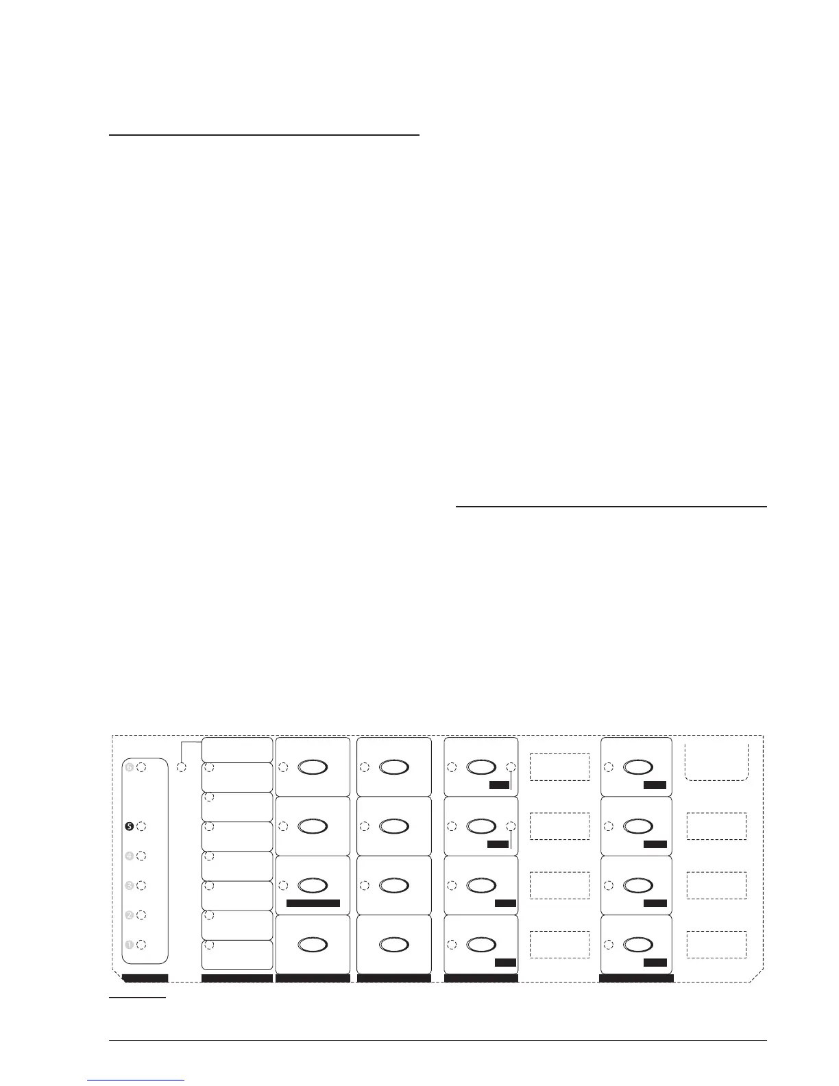
The “VARIOUS” Programming Phase
The VARIOUS LED will blink to indicate that the system
is ready to program the Stabilization Time, Reset
Time, Silenceable Outs and Configuration 1 and 2.
During this phase, the keys and LEDs will operate in ac
-
cordance with the options preceded by in the panes
on the Programming Overlay, see Figure 33.
1. Using the keys in columns C and D, select the para
-
meter you want to program, then refer to the re
-
spective paragraph or, press the Next phase key 9
to go to the following Programming Phase (see Co
-
lumn A).
48 Conventional Fire Panels J424/J408
M
M
M
M
M
M
M
M
M
M
M
M
M
M
M
M
M
M
M
M
M
M
M
M
Gas detector
N
5 sec
1 sec
C
N
2 sec
Test on NACs
NAC1 Alarm
4 sec
NAC2 Alarm
8 sec
Silen. Out R
ALARM
16 sec
OC output
160 sec
32 sec
Alarm verific.
320 sec
64 sec
640 sec
128 sec
MODULES
VARIOUS
PANEL
OUTPUTS
TIMES
ZONES
-
Refresh time
Pre-alarm
Day mode
Reset time
Zone 1
Zone 1
Fault
Exting. 1
ALARM
LCD 1
Zone 5
Zone 5
Zone 5
Power 1 Re
p
.1
Zone 2
Zone 2
Test
Exting. 2 LCD 2
Zone 6
Zone 6
Zone 6
Power 2 Re
p
.2
Zone 3
Zone 3
Zone 3
Expander 1 LCD 3
Zone 7
Zone 7
Zone 7
Power 3 Re
p
.3
Zone 4
Zone 4
Zone 4
Expander 2 LCD 4
Zone 8
Zone 8
Zone 8
Power 4 Re
p
.4
Zone 2/Extin
g
.2
-
Silenceable outs
Verification time
Reset
Ni
g
ht mode
Activation zones
-
Pre-alarm time
Alarm
User code
Extinguish. time
Stabilization time
-
Silence time
Disablement
Clock
Configuration 1
-
Confi
g
uration 2
DL output delay
Double knock
Date
12 3
45 6
78
90
Next Option
Decrease time
Next Output
Decrease time
Decrease time
-
Increase time
Mains off delay
Increase time
Increase time
Next phase
CBA E FD
Pre-alarm on R
Detect missing
Call-point alarm
NAC2 Pre-alarm
NAC1 Pre-alarm
Zone 1/Extin
g
.1
Figure 33 The “VARIOUS” Programming Phase
 Loading...