7
ASSEMBLY
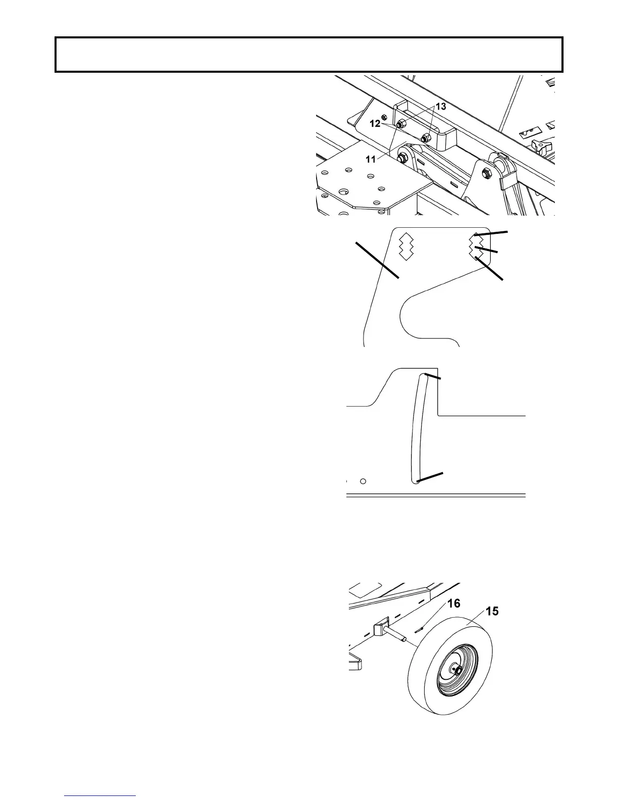
LIFT SUPPORT INSTALLATION
Remove the supports which hold the axle support in
place and assemble the lift support (item 11) to the
axle support as shown using two carriage bolts 3/8 x
1-1/4’’ (item 12) and two nuts 3/8’’ (item 13).
Use the middle hole Z on the lift support.
NOTE: Once this is done, activate the rough cutter lift
system. The sleeves (item 8, previous page) (left and
right side) must never come into contact with the top
nor the bottom of the oblong holes. If the sleeves
come into contact with the top (item A) use the Z1
holes to install the lift link.
If the sleeves come into contact with the bottom (item
B) use the Z2 holes to install the lift link. This will
guarantee a longer life of the actuator.
WHEEL INSTALLATION
Install the wheels (item 15) and secure with the cotter
pins (item 16).
Reconnect the spark plug cable.
Z1
Z
Z2
11
A
B