8
ASSEMBLY
STEP 6
CONTROL BOX SUPPORT
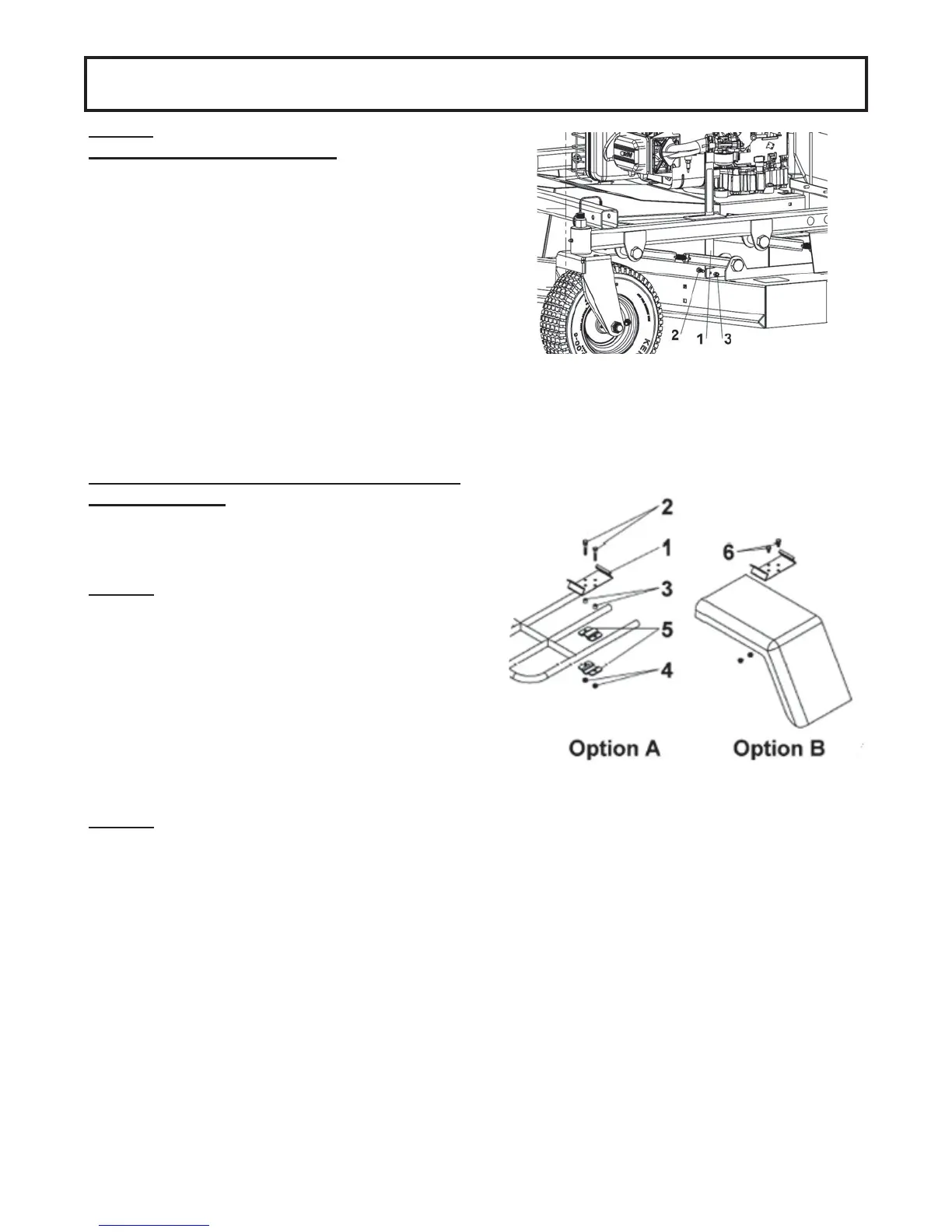
INSTALLATION
Choose between the two ways of installing the control
box support (item 1).
Option A
Use two hex bolts 1/4" x 1 1/2" (item 2), two spacers
(item 3) and two flange nuts 1/4" (item 4) to attach the
control box support to the support brackets (item 5).
NOTE: Choose the right hole combination on the
control box support in order to orient the front of the
control box towards the driving controls of the vehicle.
(see operation section to see how control box is
oriented), Furthermore, make sure to have free
access at all times to the equipment's controls in
order to safely control the equipment.
Option B
Drill two holes of 1 9/16’’ apart on the vehicle. Secure
the control box support with two bolts 1/4" x 1/2" (item
6) and two flange nuts 1/4".
Insert the control box in the control box support.
NOTE: In order to prevent damage due to water
accumulation, make sure to place the control box
horizontally.
STEP 5
HEIGHT SCALE ASSEMBLY
Install the height scale (item 1) with two bolts (item 2)
and two nuts (item 3).