6
ASSEMBLY
STEP 2
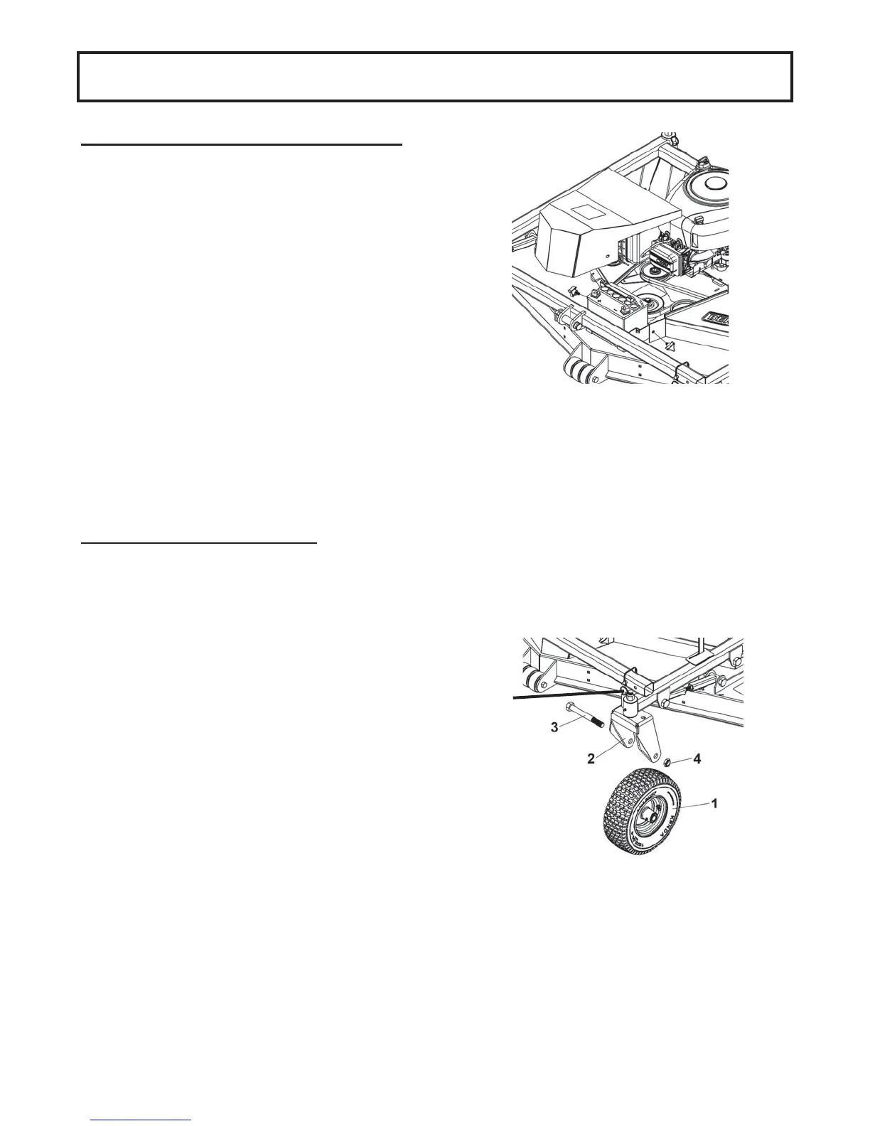
CASTER WHEEL ASSEMBLY
Assemble the four wheels on the wheel support as
shown. Insert the wheel (item 1) on the wheel support
(item 2). Secure in place using a bolt 3/4 x 6-
1/2’’ (item 3) and a thin nylon inset lock nut 3/4’’ (item
4).
Make sure there is a slight play between the wheel
fork and the bearings, this will guarantee that the
bearings are not too tight. Make sure the wheel turns
freely after completing the assembly.
Then insert the lock pins (item 5) in place to lock the
wheels.
Lock the four wheels when:
Transporting between mowing zones.
Mowing at high speed (max speed 5 mph).
Mowing in a sector that does not require tight
turns.
Lock two wheels when:
Mowing in all conditions.
No wheels are locked:
Only when the mower is used in the front.
(requires optional subframe)
Unlocking the four wheels when the mower is
attached at the back of the vehicle can cause loss
of control which will cause injuries or even death.
STEP 1
ENGINE AND BATTERY PREPARATION
Disengage spark plug wire and place it where it
cannot make a connection.
Add oil in the engine. Verify oil level and add if
necessary before starting engine. (See engine
owner’s manual).
U1 battery must be purchased locally:
Check the battery. If the battery is put into service
after the “month and year” of the date on the battery,
it may need to be charged with a 12 volt battery
charger. Follow the manufacturer's instructions for the
battery or for the battery charger.
Attach battery cables to the battery, making sure to
attach the red wire to the positive terminal first and
the black wire to the negative terminal second.
Secure in place with the rubber ties.
NOTE: It is important to put the protection cap
on the battery’s red post . Failure to install the
cap can cause injury or damage.
5