17
ENGLISH
2 DESCRIPTION OF THE APPLIANCE
2.1 Functional elements of the appliance / Max.
dimensions and connections
2.1.1 Models for indoor installation
See Fig. 16
2.1.2 Models for outdoor installation
See Fig. 17
2.2 Water circuit
See Fig. 18
2.3 Multi-row wiring diagram
NOTE: L-N POLARISATION IS RECOMMENDED
See Fig. 19
3 INSTALLATION
3.1 Standards
7KHXVHRIJDVFRQWUROER[HVLVVXEMHFWWRVWULFWUHJXODWLRQV,WLVWKHUHIRUH
important that the UNI 7129 and 7131 standards are observed.
)RUOLTXH¿HGSHWUROHXPJDV/3*WKHLQVWDOODWLRQPXVWFRPSO\ZLWKWKH
requirements of the distributing companies and with the requirements of
the standards cited above.
The appliance is sold without the inlet and outlet device as a different
GHYLFHLV UHTXLUHG DFFRUGLQJ WR WKHVSHFL¿F LQVWDOODWLRQ SOHDVHFRQVXOW
the accessories catalogue to request any of the various different devices.
3.2 Positioning
- The appliance should be installed on a suitable wall and it is essential
that the minimum distances be left around it to allow for maintenance
work to be carried out (see section ":DOOPRXQWLQJ
- The appliance should not be positioned above a stove or other cooking
appliance so as to avoid kitchen vapour grease being deposited on it
and affecting operation.
- Heat-sensitive walls such as those made from wood should be protect
-
ed with suitable insulation.
3.3 Wall mounting
3.3.1 Models for indoor installation
The appliance must be installed on a suitable wall:
- the appliance should never be closed in a unit or niche; there should be
a gap of at least 20 mm between the side walls and the appliance, so
maintenance work can be carried out
See Fig. 20
- once the position of the appliance has been established, position the
template supplied and mark the position of the holes, then remove it
and drill 2 Ø 8 holes
See Fig. 21
L
Models 11-13 250 cm
Models 17 320 cm
- UHSRVLWLRQWKHWHPSODWHDQG¿[LWZLWKWKHSOXJVVXSSOLHG
- the most common type of rear and horizontal outlet is described below;
*XLGHWKHZDOOWHPSODWH¿QVLQWRWKHVORWVRQWKHSDSHUWHPSODWH
- mark the centre of the pipe hole;
- drill a hole Ø 110 mm as indicated on the paper template
See Fig. 22 and Fig. 23
- cut the pipes to the correct length according to the thickness of the wall.
,IGRQHFRUUHFWO\WKHPPÀXHSLSHVKRXOGSURWUXGHE\PPZLWK
respect to the 100 mm Ø air duct
- LQVHUWWKHVSHFL¿FSLSHPDGHXSRIWZRFRQFHQWULFSLSHVLQWKHKROHLQ
the wall
See Fig. 26
- seal the gap between the 100 Ø pipe and the hole in the wall with ce
-
ment-based mortar, positioning a piece of paper so that the tube does
QRW
UHPDLQ¿[HGWRWKHZDOOLWVHOIVRDVWRIDFLOLWDWHVXEVHTXHQWGLVDV-
sembly. Place the appliance in the chosen position, with reference to
the
measurements
indicated in this instruction booklet in the “Func-
tional elements of the appliance / Max. dimensions and connections”
section.
3.3.2 Models for outdoor installation
The appliance has been designed only for installation outdoors in an area
that is partly covered. For this reason it must be installed in the open,
outdoors with natural aeration and ventilation, without stagnant zones for
combustion products, which should be rapidly dispersed by means of nat
-
ural convection or by the wind.
The discharge outlet of the appliance should be free of obstructions, ob-
MHFWV
RUERGLHVWKDWFRXOGSUHYHQWLWIURPH[SHOOLQJWKHÀXHJDVHVFRUUHFWO\
and protected from an contacts during or after operation: it is possible it
overheats and cause burns.
Fig. 24: example of an
INCORRECT
evacuation of the products of the
FRPEXVWLRQLQVLGHDEDOFRQ\FORVHGRQ¿YHVLGHV
See Fig. 24
When the appliance is being installed the minimum distances of the dis
-
charge/suction line must comply with current local legislation, having re-
gard for any other appliances installed, openings, architectonic elements,
and boundaries.
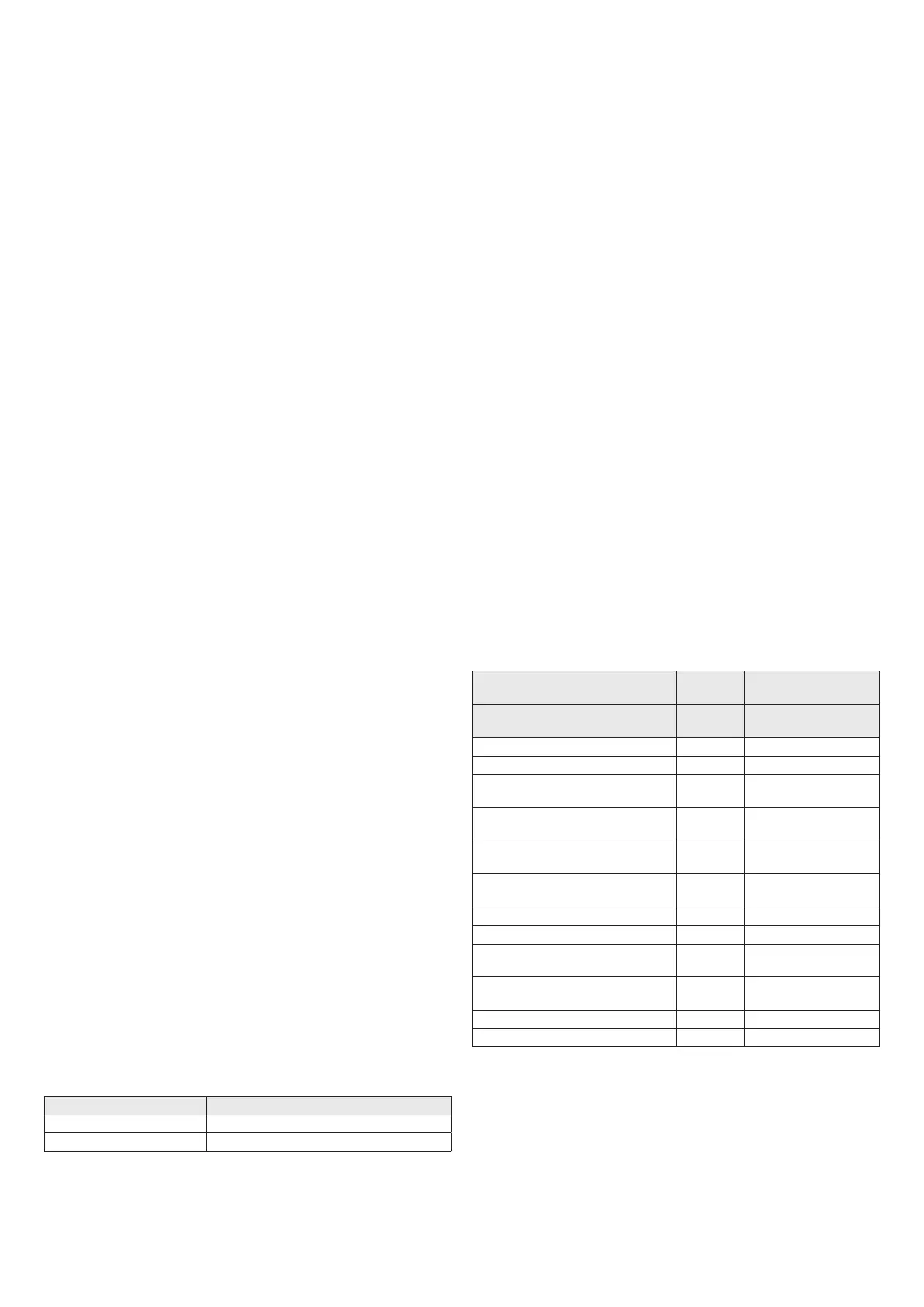
Positioning the terminal Position
Minimum distances
(mm) (*)
Appliances over
16kW up to 35kW
Under a window A1 600
Next to a window A2 400
Under an aeration/purging open
-
ing
B1 600
Next to an aeration/purging
opening
B2 600
9
HUWLFDOGLVWDQFHEHWZHHQWZR
discharge terminals
C1 1.500
+RUL]RQWDOO\DGMDFHQWWRDGLV
-
charge terminal
C2 1.000
Under a balcony D1 300
Beside a balcony D2 1.000
From the ground or from another
walkway
E 2.200
From piping either vertical or
KRUL]RQWDOGLVFKDUJHV
F 300
Under the eaves G 300
Corner/recess/wall of the building H 300
(*)
For type A appliances the minimum distance coincides with the cen-
tre of the outlet section for combustion products going into the air.
(**)
When positioning the appliance distances of not less than 500
mm must be adopted from materials sensitive to the action of the
combustion products (for example, plastic eaves and drainpipes,
SURWUXGLQJZRRGHOHPHQWVHWFIRUVPDOOHUGLVWDQFHVXVHVXLWDEOH
screening with regard to said materials.
 Loading...