, Gas Combustion air system
Page 1 : 1
2.02
0611 BC
COMBUSTION AIR SYSTEM
The engine normally is equipped with a filter silencer
on the turbocharger, and combustion air is drawn
from the engine room.
According to DnV rules all components are to be
designed to operate under the following environ-
mental conditions:
• Ambient air temperature in the machinery
space between 0°C and 55°C
(for engine air inlet max. 45°C).
• Relative humidity of air in machinery space up
to 96% (for engine air inlet max. 60%).
• Sea water temperature up to 32°C
As a result of the above requirements all our engines
are now designed to operate with intake air
temperature down to 0°C, without any charge air
blow-off arrangement.
If expected intake air temperature is lower than 0°C,
the engine must have a charge air blow-off system,
which shall come into action at 10°C.
Ducted combustion air intake
When it is required to draw combustion air from out-
side of machinery space the turbocharger will be
equipped with an air suction branch.
In design of the system, the following must be taken
into consideration:
• Total pressure loss in the system must not
exceed 100 mm WG (water gauge).
• Radius on pipe bends to be 2 x Dpipe
• It must not be possible for any particles or water
droplets to enter the turbochargers compressor.
At the end of the ducting (air intake) a fabric
filter with a mesh less than 1 mm it must be
fitted a to prevent entry of foreign particles.
• The ducting must be completely clean inside
and preferably made of stainless steel.
• The ducting must contain a baffler designed for
required noise level at combustion air intake.
• Drain pockets should be fitted to prevent water
from coming into the engine.
Fitting the air inlet pipes.
The ducting air must be connected to the
turbocharger with the compensator supplied by
Rolls-Royce.
The compensator must be connected directly to the
air suction branch.
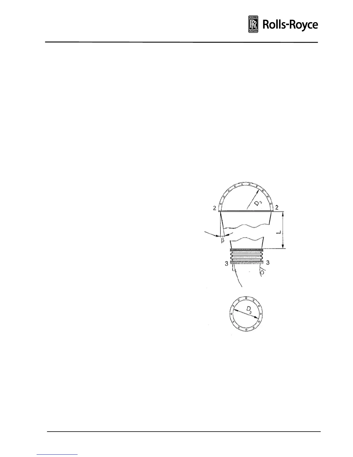
A straight piece of duct must be inserted immediate-
ly before the compensator, the passage cross-section
of which at 2-2 must be at least 20% greater than at
3-3 (see fig. below).
The straight piece of duct must have a minimum
length L of 2 x D
2-2
(see fig. below).
The pipes should be fixed so that they cannot
vibrate. The inlet pipe suspension must be arranged
with a fixed point as close as possible to the
compensator on the engine.
The exhaust and inlet pipes should be arranged so
that assembly and disassembly of the insulation, and
dismantling and fitting of the silencer and air outlet
casing with the bearing casing are not impeded.