, Gas Ignition system
Page 1 : 1
3.03
0116 BC
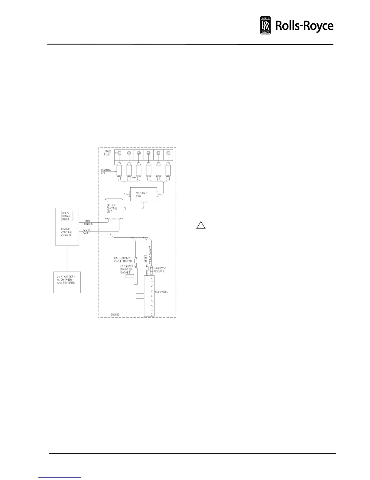
IGNITION SYSTEM
The ignition system consists of a 24 V DC solid state
electronic Central Processing Unit (CPU), pick-ups,
a junction box, individual coils for each cylinder and
spark plugs.
All components for the ignition system with the ex-
ception for the ignition on/off sequence control and
the 24 VDC power supply are attached to the engine.
See figure below.
Fig. 1 Ignition system L 771/93
The CPU-95 unit distributes low voltage energy
(180 V) to the coils, which again supply high voltage
energy (Max 40000 V) for the spark plugs.
Short high-voltage leads take the energy from coils
to the spark plugs.
The ignition timing are controlled by two magnetic
pick-ups on the flywheel and one pick-up on the
camshaft. The pick-ups on the flywheel sense 180
holes and a reset pulse for the most advanced firing
point and thus determining the correct angular
position to release the ignition according to the
firing order.
The pick-up on the camshaft resets the system for
every complete 4-stroke cycle and thereby separates
the firing from the scavening stroke.
The ignition timing for standard engines are manual-
ly set from CPU-95 display module.
The ignition on/off is automatic controlled by the
start/stop sequences and safety system in the engine
control cabinet.
With the exception of the high-voltage leads and the
spark plugs all ignition system components and ca-
bles on a standard engine are shielded for operation
in Ex-proof zones.
Options:
• Shielded spark plugs and high-voltage leads for
operation in Ex-proof zones.
• For special engine application, automatic
timing in accordance with the load/RPM.
By special customer request only, battery with charger and
rectifier is included in BEAS scope of supply.