Ventilation system
Page 2 : 2
2.04
, Gas
0611 BC
Gas regulating unit (stop valve and gas control valve
for main gas supply, stop valve and control valve for
pre chamber gas, filter sensors etc.) is positioned in a
safe, ventilated area in a separate compartment in
the engine room. The compartment has a gas detec-
tion sensor.
Both the main gas pipe and the prechamber gas
pipe are positioned on the engine on the opposite
side of the exhaust system.
On a ship with engines running on LNG the usual
gas supply system consist of a gas regulating unit
(GRU) connected to the engines gas manifold
through a relatively long gas supply pipe.
On the GRU a "Block and Bleed" (BnB) system is
included. The BnB system task is to empty the gas
supply pipe and gas manifold of fuel gases, and also
stop more gas entering the supply pipe from the
GRU, during and after an engine shut down. Mean
while the BnB system shuts off the gas supply from
the GRU, the last engine cycles are used to pump
out any remaining gas that is trapped between the
engines gas flow control (GFC) valves and inlet ports.
A normal engine shut down procedure, as described
above, is sufficient enough to prevent any fuel gases
from entering the engines intake receiver, and there-
by also preventing any gas seeping out past the
compressor wheel and entering the ships engine
room.
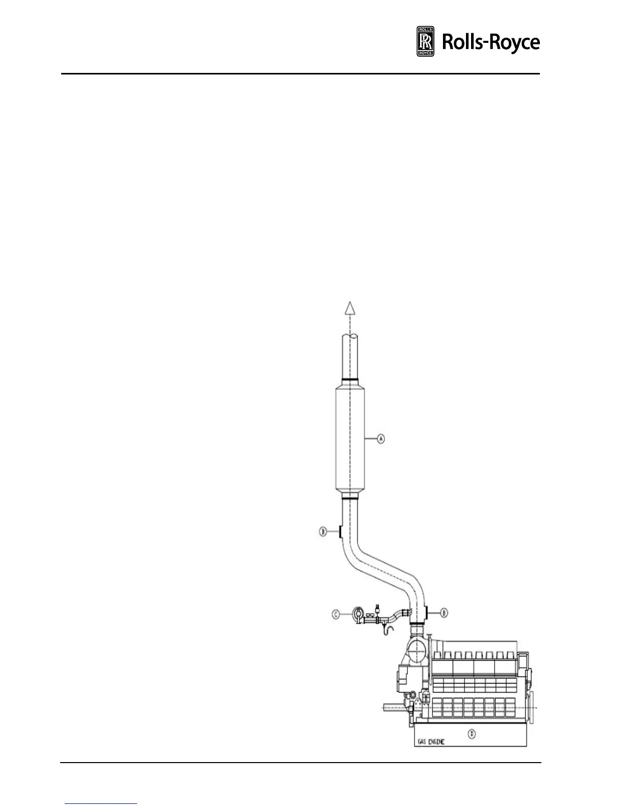
Safety precautions
Fuel gas may enter the exhaust system through the
engine as a result of one or more malfunctions.
If there is a source of ignition present, the gas may
become ignited. This enforces that the exhaust
system is designed so that the pressure build up,
in the case of such event, does not exceed the
maximum pressure level of the components in the
system. Silencer and engine mounted exhaust
bellow are designed for a max pressure of 1 barg
This will normally result in a requirement for fitting
safety devices to the exhaust system, such as pres-
sure relief valves or rupture discs, to limit any explo-
sion pressure.
The size, number and positioning of such devices
should be verified by calculation or simulation in
each case, subject to classification approval if re-
quired.
The discharge of such devices should be led to a safe
place remote from any ignition sources. The dis-
charge may consist of combustion gases or un-
burned fuel depending on the propagation of
uncontrolled combustion inside the exhaust system.
The extension of the safe zone with respect to hot
exhaust gases depend very much type of safety
device – with flame arresters this can be reduced
significantly.
In order to reduce the risk of accumulating fuel in
the exhaust system, the piping and all other
components in the exhaust system should have a
constant upward slope. Silencers, boilers and other
equipment should be designed such that no fuel
gas can accumulate inside.