EN
10
Resistance and Continuity Measurements
Insert the black test lead into the negative COM terminal and the red test lead into the
positive terminal.
Set the function switch to the
position.
Use the multifunction MODE button to select resistance.
Touch the test probe tips across the circuit or component under test. It is best to disconnect
one side of the device under test so the rest of the circuit will not interferewith the resistance
reading.
For Resistance tests, read the resistance on the LCD display.
For Continuity tests, if the resistance is < 100 , a tone will sound.
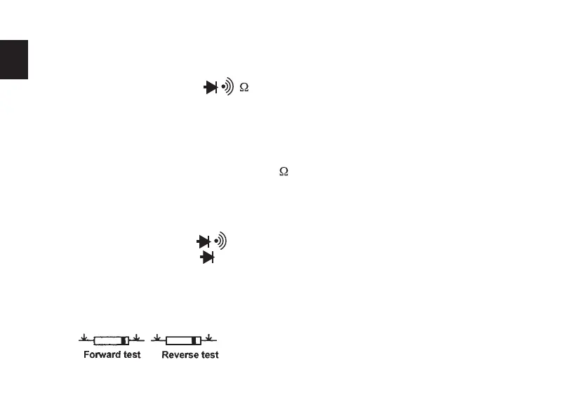
Diode Measurements
Insert the black test lead banana plug into the negative COM jack and the red test lead banana
plug into the positive diode jack.
Turn the rotary switch to the
position.
Press the MODE button until appears in the display.
Touch the test probes to the diode under test. Forward voltage will indicate 0.4V to 0.7V.
Reverse voltage will indicate “OL”. Shorted devices will indicate near OmV and an open
device will indicate “OL” in both polarities.
1
2
3
4
5
6
1
2
3
4
Red probe Red probe
Black
probe
Black
probe

 Loading...