5
HTE402559 34/47
Note: Two external rheostats or a current control must have been wired before the function
cord “rnt X” will be set for “X=2” or “X=1”.
Note: “Panel” in the table means running by stored data, the stroke and
the driving frequency.
Note: On the maximum setting of the external rheostat the stroke data appears
on the display is not “100” but “over 95”.
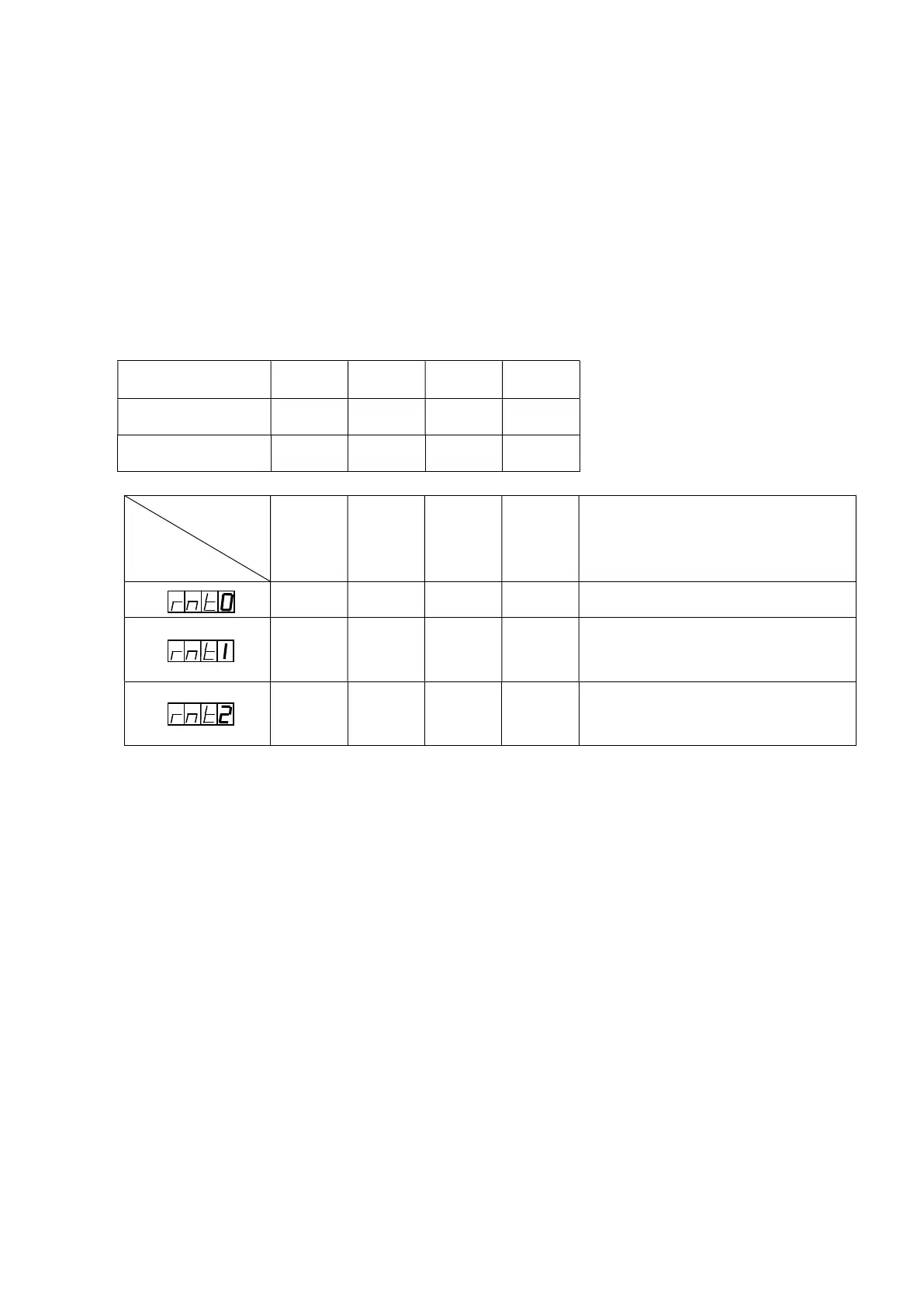
Combination No.
Function code
0 1 2 3 Remarks
Panel Panel Panel Panel Running by the stored data
4-20mA
Panel Panel Panel
The Combination No.0 determines
running by 4 – 20 mA current
control.
VR1 VR2 Panel Panel
The combination No.1 and 2
determine running by the external
rheostats. See note below.
Speed Change Signal
Combinations of “Open” or “Close” between terminals “COM” and“N1”, and “COM” and “N2”,
with contacts provided by customer, determines “Combination No.” See table below.
Combination of “Combination No.” and Function “Remote” determines behavior of VMC-controller.
Combination No. 0 1 2 3
N1 and COM Open Close Open Close
N2 and COM Open Open Close Close