INSTALLATION MANUAL
2) GENERAL OUTLINE
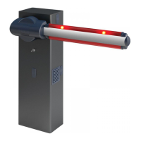
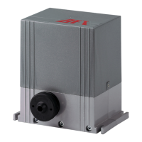
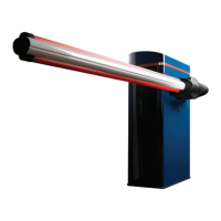
Compact electromechanical barrier suitable for limiting private areas, park-
ings, access areas for vehicles only. Available for passageways from 4 to 8
metres. Adjustable electronic limit switches, they guarantee correct boom
stopping position. In case of intensive use, a thermal sensor activates the
cooling fan.
The emergency release device for manual manoeuvre is controlled by a
personalised key lock.
The actuator is always supplied for left-hand side tting. However, when nec-
essary, the opening direction can be reversed by means of simple operations.
The BM mod. foundation base (on request) makes barrier installation easier.
Appropriate ttings make it easy to install accessories.
The LIBRA C MV control panel is supplied by the manufacturer with standard
setting. Any change must be set by means of the incorporated display or by
means of the universal programmer.
3) TECHNICAL SPECIFICATIONS
Power supply: 230V±10% 50/60Hz(*)
Power absorbed: 300W
Absorption (with accessories): 1 A
Internal lubrication:
permanent grease
Max torque: 600 Nm
Opening time: 6s (5-6m), 8s (8m)
Boom length:
4m (MICHELANGELO 40)
5-6m (MICHELANGELO 60)
da 6m a 8m (MICHELANGELO 80)
Impact reaction: encoder
Manual mechanical release: customised key
Type of boom: rectangular/round
Limit devices:
electrical incorporated and electroni-
cally adjustable
Type of use continuous operation
Working temperature: from -20°C to +55°C
Degree of protection: IP 24
Operator weight (without boom):
55 Kg (MICHELANGELO 40)
58 Kg (MICHELANGELO 60)
68 Kg (MICHELANGELO 80)
Dimensions: see g. A
Mains/low voltage insulation: > 2MOhm 500V
Dielectric strength:
mains/low voltage 3750V~ for 1
minute
Motor output current:
20A max (MICHELANGELO 40)
25A max (MICHELANGELO 60)
30A max (MICHELANGELO 80)
Cooling intervention
temperature:
80°C
Supply to accessories: 24V~ (180 mA max absorption)
Barrie-open warning light: 24V~ 3W max
Blinker: 24V~ 25W max
Fuses: see gure I-L
N° of combinations:
4 billion
Max. n° of remotes that
can be memorized:
63
(*)= special power supply voltages on request.
Usable transmitter versions:
All ROLLING CODE transmitters compatible with
4.1) FOUNDATION PLATE (Fig. B1).
4.2) FASTENING ANCHOR BOLTS (Fig. B2).
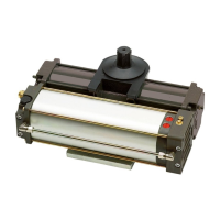
5) FITTING OF THE ACTUATOR
WARNING! The barrier must be exclusively used for vehicles to
drive through. Pedestrians must not walk within the operator
manoeuvring area. An appropriate pedestrian passageway must be
provided for.
The passageway must be suitably indicated by means of the warning
signs illustrated in Fig.A.
WARNING: before opening the door, the spring must be unloaded
(vertical boom). The door of the box must be facing towards the inside
of the property. When you stand in the middle of the passageway, facing
outwards, if the box is on your left, the barrier is left-hand tted, if the box
is on your right, the barrier is right-hand tted.
The actuator is always supplied for left-hand side tting.
5.1) COVER AND DOOR OPENING AND CLOSING (Fig. D).
5.2) POSITIONING OF ENCLOSURE FIG.E
5.3) BOOM FIXING (Fig. F).
6) MICHELANGELO 40-60 accessories: boom length limits and balancing
(Fig. G1).
For further information about the installation and use of accessories, refer
to the respective instruction manuals.
6.1) MICHELANGELO 80 accessories: Fig.G2.
6.2) BAR BALANCING (Fig. G3).
6.3) ATTACHMENT AND TENSIONING OF SPRING g. AC-AD
7) Right-hand tting (Fig. AA, AB)
- Carry out bar balancing as described in Fig. G3.
- Set the Direction Reversal logic to ON in the control panel.
Warning: the Direction Reversal logic must be congured to OFF for
left-hand tted barriers, and to ON for right-hand tted barriers.
Otherwise, the limit devices will not operate or an encoder direction
error will be displayed.
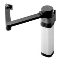
8) FITTING THE FLASHING LIGHT (FIG AE - AF)
Complete assembly and wiring as directed in instructions provided for
the ashing light
9) FITTING THE PHOTOCELL (FIG AF).
Complete assembly as directed in instructions provided for the photocell
----------------------------------------------------------
10) ELECTRICAL INSTALLATION SET-UP
WARNING: before opening the door, the spring must be unloaded (ver-
tical boom). Set up the electrical installation (g. A) with reference to the
current regulations for electrical installations. Keep the mains power supply
con-nections denitely separate from the service connections (photocells,
electric edges, control devices etc.).
Warning! For connection to the mains, use a multipolar cable having
minimum 3x1.5mm
2
cross section and complying with the previously
mentioned regulations (for example, if the cable is not protected, it
must be at least equal to H07 RN-F, whereas if it is protected it must be
at least equal to H07 VV-F with a 3x1.5 sq mm
2
cross section).
Fig. A shows the number of connections and section for a 100m length of
power supply cables; for greater lengths, calculate the section for the true
automation load. When the auxiliary connections exceed 50 metre lengths
or go through critical disturbance areas, it is recommended to decouple the
control and safety devices by means of suitable relays.
The main automation components are (g. A):
I) Type-approved adequately rated omnipolar circuit-breaker with
at least 3,5 mm contact opening, provided with protection against
overloads and short circuits, suitable for cutting out automation from
the mains. Place, if not al ready installed, a type-approved dierential
switch with a 0.03A threshold just before the automation system.
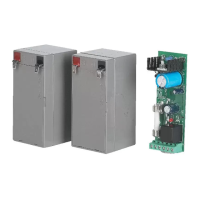
QR) Control panel and incorporated receiver.
S) Key selector.
AL) Blinker
M) Actuators.
A) Bar.
F) Rest fork.
CS) Electric edge.
Ft,Fr) Pair of photocells.
CF) Photocell post.
T) 1-2-4 channel transmitter.
RMM) Inductive metal mass detector.
LOOP) Mass detector loops.
11) CONNECTION (FIg. H-I)
ENGLISH
MICHELANGELO - 25
D812001 00100_03
 Loading...