EasyManua.ls Logo

BGW 8000 - Service and Maintenance; Module Servicing Procedures

Default Icon
41 pages
Print Icon
To Next Page IconTo Next Page
To Previous Page IconTo Previous Page
Loading...
-
'/~"
13600
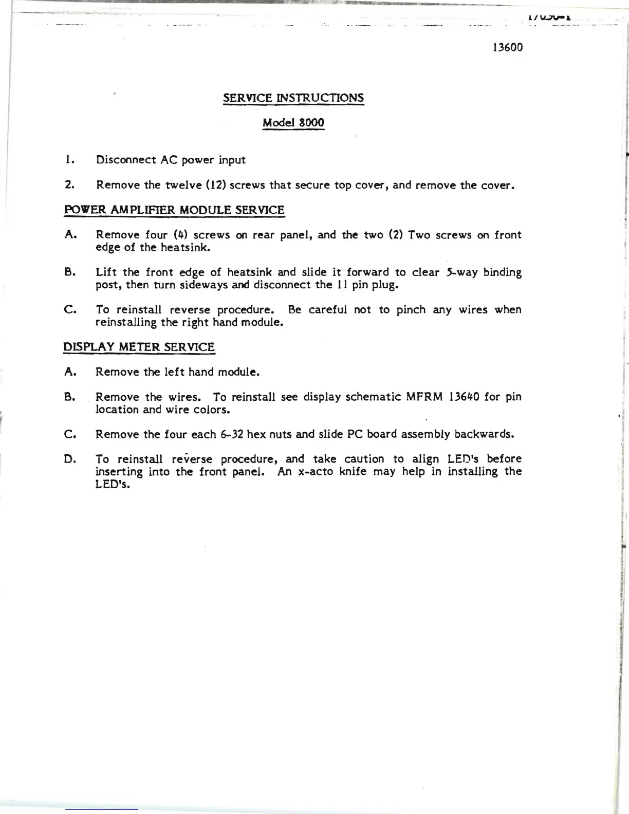
SERVICE INSTRUCTIONS
Model 8000
1.
Disconnect
AC
power input
2. Remove
the
twelve
(l2)
screws
that
secure
top cover, and remove
the
cover.
POWER
AM
PUFlER
MODULE
SERVICE
A. Remove four
(4)
screws
on
rear
panel, and the two
(2)
Two screws
on
front
edge
of
the
heats
ink.
B.
Lift
the
front
edge
of heats ink and slide
it
forward to
clear
5-way binding
post, then turn sideways
and disconnect
the
11
pin plug.
C.
To
reinstall
reverse
procedure.
Be
careful
not
to
pinch any wires when
reinstalling
the
right
hand module.
DISPLAY
METER
SERVICE
A. Remove
the
left
hand module.
B.
. Remove
the
wires. To reinstall see display
schematic
MFRM
13640 for pin
location and wire colors.
C.
Remove
the
four
each
6-32 hex nuts and slide PC board assembly backwards.
D.
To
reinstall
reverse
procedure, and
take
caution to align LEO's
before
inserting into
the
front
panel. An
x-acto
knife may help
in
installing
the
LED's.