Do you have a question about the BGW 150 and is the answer not in the manual?
Covers power off connections, fuses, output connections, voltage mains, cover removal, and service procedures.
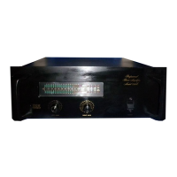
Details the function of IDLE and clipping indicators, and audio level indicators on the front panel.
Explains separate circuit and chassis grounds, and the use of a removable link for ground loop elimination.
Describes the use of XLR and 1/4 inch phone jacks, including transformer socket connections.
Notes the need for side rails or rack shelves for proper amplifier support in rack installations.
Details advanced transistors, heat sink contact for bias stability, and stacking capability.
Discusses voltage gain circuits, operational amplifier front end, and Darlington voltage follower output.
Details minimum sine wave continuous average power output for 8 and 4 ohm loads and monaural operation.
Covers intermodulation distortion, frequency response, hum/noise, input sensitivity, impedance, and power requirements.
Lists semiconductor complement, dimensions, and weight including shipping weight.
Instructions on saving the original container and inspecting the unit for transit damage upon receipt.
Emphasizes careful mounting for unrestricted airflow to prevent overheating and unit shutdown.
Crucial instruction to make all connections before applying power to the amplifier.
Discusses natural convection, forced-air cooling, spacing, chimneys, and ventilation vents for rack installations.
Guidance on placing heaviest units at the bottom, using blank panels, and ensuring proper support.
Describes use for unbalanced lines only, with details on connecting shield to sleeve and conductor to tip.
Explains use for balanced or unbalanced lines via transformer sockets, and connection requirements.
Details using a jumper plug in transformer sockets for unbalanced lines via XLR connectors.
Discusses using transformers for true balanced inputs and refers to specific forms for selection.
Refers to specific forms for connecting one source to two or more amplifiers or devices.
Instructs to use the left channel input only for mono operation and set the stereo/mono switch.
Details using 1:1 transformers and terminating resistors for multiple balanced line inputs.
Specifies adding a terminating resistor to the octal plug for bridging unbalanced line inputs.
Explains using 1:5 or 1:1 transformers for single balanced inputs, with 600 ohm termination requirements.
Details the requirement for a 600 ohm terminating resistor on the octal plug for single unbalanced inputs.
Provides a step-by-step method to find the required terminating resistance for 600 ohm lines.
Guides on connecting speakers to left/right binding posts, ensuring proper phasing and polarity.
Recommends fuse protection for speakers and provides a nomograph for selecting the correct fuse value.
Explains how wire length/size affects damping factor and how to calculate it; notes impedance estimation method.
Details setting the stereo/mono switch, using the left channel input, and connecting outputs to red binding posts.
Explains how the left channel inverts and drives the right channel for doubled output voltage swing.
Guides on verifying mains voltage, plug type, and understanding the power cord color-coding.
Covers speaker protection, preventing ground loops, voltage limits, avoiding corrosive environments, and safe operation.
Details the correct order for powering on the preamplifier and the power amplifier, checking the idle indicator.
Provides steps for adjusting power amplifier gain controls and preamplifier gain for desired volume.
Addresses turn-on transients from pre-amps or tuners, suggesting powering on the amplifier last.
Explains the AC input path through circuit breaker, transformer, rectifier, and filter capacitor stages.
Details the signal path from input level control through op-amp, drivers, output stages, and protection networks.
Describes how the mono/stereo switch configures the right channel amplifier for unity gain inverting operation.
Illustrates the overall internal wiring connections of the Model 150 amplifier.
Provides an alternative view or detail of the amplifier's internal wiring connections.
Shows wiring configurations for different mains voltages (100-240V) and associated circuit breakers.
Presents alternative wiring diagrams for domestic and foreign voltage configurations.
Lists part numbers for various types of capacitors including electrolytic, mica, mylar, and disc capacitors.
Explains component numbering schemes (100, 200, 300, 400 series) for heatsink and chassis components.
Lists part numbers for various diodes, including Zener diodes, and bridge rectifier assemblies.
Lists part numbers for integrated circuits such as level detectors, timers, and operational amplifiers.
Provides part numbers for various input/output jacks, pin sockets, and XLR connectors.
Lists part numbers and types for NPN and PNP transistors used in the amplifier.
Lists part numbers, values, tolerances, and types for deposited carbon and metal film resistors.
Lists part numbers for thermal switches, slide switches, and toroidal transformers.
Provides part numbers for terminal strips, ground barrier strips, and miscellaneous items like knobs.
Lists various hardware items including screws, washers, nuts, insulators, and heat shrink tubing.
Details warranty period, what is covered, how to obtain service, and common exclusions.
Explains limitations on implied warranties, consequential damages, and specific consumer rights.