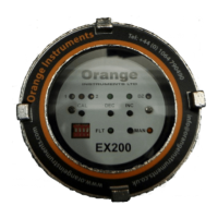
EX200 Electro-Hydraulic Actuator Positioner
Bifold Orange Limited.
Drwg. No.: ORM0001 Issue : 1 Date : 24/06/2015 Page : 13 of 20
Specification
COMMAND SIGNAL INPUT
4-20mA nominal 240R input impedance
ANALOGUE POSITION OUTPUT SIGNAL
0.5-22mA can be calibrated anywhere in this range. Sourcing 12V max load 400R. Sinking 12-30V excitation
FEEDBACK SIGNAL INPUT
Potentiometer 3-wire, any value greater than 200R
4-20mA nominal 240R input impedance
SWITCHED OUTPUTS x 5
Maximum 3A for each output (max controller volt drop at 3A = 0.27V)
INSTRUMENT AND SOLENOID SUPPLY
DC unit - 24Vdc (15-36V absolute maximum range) - 1.3W excluding solenoids, 55mA maximum current drawn in normal
use
AC Unit - 115/230V 50-60Hz – 11W
USER ADJUSTMENTS
DEC Button to close actuator in Manual
INC Button to open actuator in Manual
MAN Button to toggle auto/manual mode
CAL Button to select Calibrate mode and store calibration data
Timer setting
DIP Switch 1 - Set stepping timers – DECREASE ON and OFF
DIP Switch 2 - Set stepping timers – INCREASE ON and OFF
DIP Switch 3 - No function
DIP Switch 4 - No function
Normal operation
DIP Switch 1 - Select continuous operation on fault if in stepping mode
DIP Switch 2 - No function
DIP Switch 3 - Select stepping mode timers
DIP Switch 4 - Select stepping mode
DZ Potentiometer to set positioning dead zone - clockwise to increase
CAL1 Calibration adjustment and ON time for stepping mode
CAL2 Adjustment for OFF time for stepping mode
INTERNAL LINKS
Output sense - one position + or - must be selected for each output, even if the output is unused
LINC + and - Increase solenoid sense links
LDEC + and - Decrease solenoid sense links
LESD + and - Auxiliary solenoid sense links
LFLT + and - Fault output sense links
Other function links for “Standard” Communication
LK1 A Positioner default mode select
LK1 B Positioner default mode select
LK1 C Hydraulic pump control mode select
LK1 D Fault output interlocks
Other function links for “Hart” Communication
LKA Hydraulic pump control mode select
ENVIRONMENT
Operating temperature -40ºC to +85ºC
Storage temperature -40ºC to +115ºC
PERFORMANCE - the following applies to the EX200 only, characteristics of the feedback element and actuator system
response will have additional effects.
Conversion 10 bit max normal conversion range (4-20mA) = 1 in 800.
O/P switch res. +/-1 bit theoretically, modified to up to +/-5% of span by dead band.
Accuracy (Theo.) 0.125% span based on conversion resolution of 1 in 800.
Accuracy (actual) 0.5% span based on 25% turn down of feedback range.
HART Revision 7 + 16 bit Manufacturers and Device ID


 To Next Page