119293 4-1 REV E
POWER UNIT MAINTENANCE
Steering Adjustments
Steering control lever neutral adjustment
The mower’s steering has been factory adjusted to elimi-
nate creeping when the steering control levers are in the neu-
tral position. However, should the mower begin to creep, the
steering control lever linkage can be adjusted.
Before considering any adjustment, check the tire air pres-
sure. Unequal tire pressure will cause the mower to drift to
one side. Refer to tire pressure information in the Tire section
for detailed information.
NOTE: Proper park brake adjustment must be completed
before the steering control lever neutral adjustment can be
done. Refer to the Park Brake Spring Adjustment section for
detailed information.
Fine adjustment to the unit’s steering is made with the
transmission’s control rod.
Neutral is properly adjusted when the steering control
levers are in the park brake position and the transmissions
do not “whine”.
If this occurs, the steering control linkage may be adjusted
as follows:
1. Shut engine off, place steering control levers in the
park brake position, disengage deck clutch, remove
ignition switch key and disconnect negative battery
cable before doing any adjustments.
2. Raise the rear of the mower and block with certified
jack stands. Remove the rear wheels.
3. Chock the front tires.
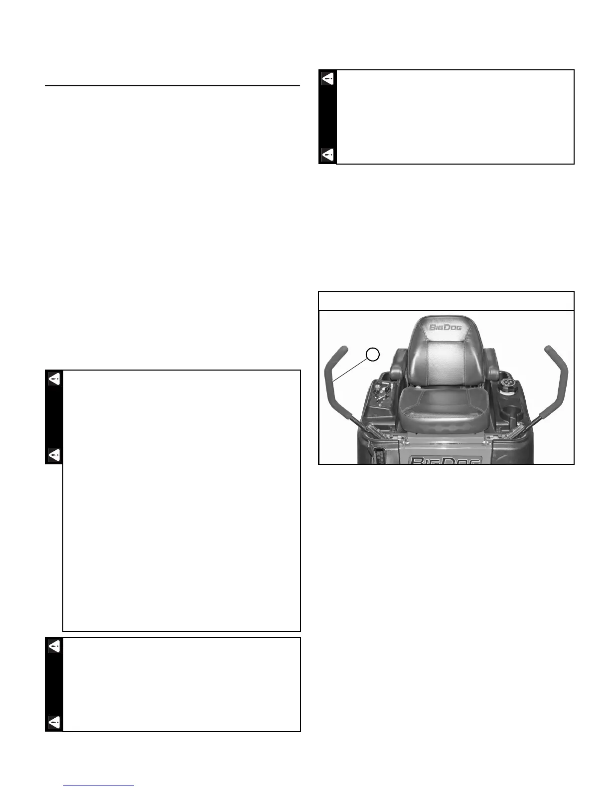
4. Make sure both steering control levers are in the park
brake position. Figure 4-1
5. Loosen the nuts adjacent to the steering bushing.
Figure 4-2
6. Place a clamp on the transmission pump arm as
shown in Figure 4-3.
7. Tighten the nuts against steering bushing (Figure 4-2).
Verify that the pump arms are still in the neutral posi-
tion.
8. Move the steering control levers out of the park brake
position and push fully forward, verify that the pump
arm does not bottom out against the stop on the trans-
mission. Move the levers to the full reverse position
and release. Verify that the levers return near to the
neutral position.
9. The steering control levers should be adjusted so that
they align vertically with each other when in the neu-
tral position (Figure 4-4). Space between ends of steer-
ing control handles to be .50" ±.25". Figure 4-4
10. Check to make sure all tools or obstructions are
removed from under the mower.
Never work under the machine or attachment
unless it is safely supported with jack stands.
• Make certain machine is secure when it is
raised and placed on the jack stands.
• Use only certified jack stands. Use only
appropriate jack stands, with a minimum
weight rating of 2000 pounds (907 kg) to
block the unit up.
• Use in pairs only.
• Follow the instructions supplied with the
jack stands.
• The jack stands should not allow the
machine to move when the engine is running
and the drive wheels are rotating.
• Do not allow the wheels to come in contact
with the floor or any object that would permit
the unit to propel itself.
• To prevent injury stay clear and exercise cau-
tion when rotating the wheels.
Keep hands, hair, clothing, etc., clear of the pulleys
on top of the transmissions. Exercise extreme cau-
tion.
Untrained maintenance personnel should never
attempt to make any adjustments or repairs to the
mower’s drive system while the engine is running.
The following procedures should be performed by
trained maintenance personnel only.
Steering control levers in park brake position
Figure 4-1