Fixed Wireless/Wired IP Camera
List of Figures and Tables
Figure 2-1: Major components in the front panel
Figure 2-2: Major components in the back panel
Figure 2-3: IP CAM connection diagram.
Figure 2-4: Connect Ethernet cable to a switch/router.
Figure 2-5: The installation CD disk
Figure 2-6: The ID/Password card
Figure 2-7: Running window of CamView program
Figure 2-8: Pop-up play-video password window
Figure 2-9: Unplug the Ethernet cable to enable the WiFi function
Figure 3-1: Open the web configuration page from CamView software
Figure 3-2: IP CAM Web configuration login page
Figure 3-3: IP CAM Information page
Figure 3-4: Video display page
Figure 3-5: Network settings page for DHCP function
Figure 3-6: Network settings page for fixed IP address
Figure 3-7: WiFi security disabled page
Figure 3-8: WiFi security enabled page
Figure 3-9: WiFi testing page
Figure 3-10: Advanced network settings page
Figure 3-11: Video settings page
Figure 3-12: 3GPP/RTSP enabled page
Figure 3-13: Motion detection enabled page
Figure 3-14: Led Control settings page
Figure 3-15: System date/time settings page
Figure 3-16: Admin settings page
Figure 3-17: Firmware upgrade settings page
Figure 3-18: Firmware upgrade status page
Figure 3-19: System reboot settings page
Figure 3-20: System reboot under-going page
Figure 3-21: Safe mode information page
Figure 3-22: Stick the reset button to set to the factory default
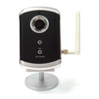
Figure 5-1: IP Camera body
Figure 5-2: Power Adaptor
Figure 5-3: Bracket
Figure 5-4: Antenna
Figure 5-5: Quick installation guide
4