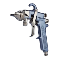
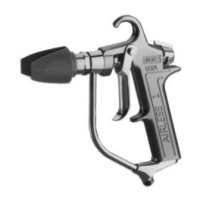
Binks Model 21 (BRASS BODY) AUTOMATIC SPRAY GUN
INTERNAL MIX HEAVY MATERIAL NOZZLES (OPTIONAL)
HOOK-UP
1. Air pressure of 50-60 PSI minimum required for cylin-
der operation.
2. For rapid operation, the air line between three-way
valve and the cylinder operating air connection should
be as short as possible.
3. All air supplied to the gun should be dirt and moisture-
free. An oil and water extractor mounted in the air
supply line is recommended.
4. If the gun is to stand idle for any length of time, shut
off. This will prevent small leaks throughout the
system from turning on the gun.
FAN SPRAY ADJUSTMENTS
The fan spray is easily controlled by means of the side
port control stem, (22). Turning this control to the right,
or clockwise, will give a round spray pattern. Turning it
to the left, or counter-clockwise, will widen the spray into
a fan shape of any desired width. Orientation of the fan
spray either horizontally or vertically (or to any position
in between) is obtained by loosening the retainer ring,
rotating the air nozzle to the desired position, and then
tightening the retainer ring.
FLUID FLOW ADJUSTMENTS
For best results, the fluid control screw (18) should be set
at the open position and the flow of the fluid controlled
by regulating the fluid pressure in the pressure tank. If
the conditions under which the gun is being used require
the fluid to be controlled at the gun, it may be accom-
plished by loosening locknut (19) and turning screw (18)
to the right (clockwise) to decrease the flow of fluid or
the left (counter-clockwise) to increase the flow of fluid.
LUBRICATION
The points that require lubrication on this gun are the
plunger (7), the air valve packing (11), and the fluid
packing (36). These parts should be kept soft and pliable
at all times. A light machine oil is recommended for this
lubrication.
CLEANING
Shut off the air supply to the tank and release its pressure.
Hold a piece of wadded cloth over the gun nozzle and
turn on the air to the cylinder. The air will back up
through the fluid nozzle and force fluid out of the hose
and into the tank.
Replace the paint in the pressure tank with clean solvent
and spray the solvent through the gun until it is clean.
Dry out the residual solvent in the fluid hose by blowing
air through it.
FAULTY SPRAY
Faulty spray is caused by dry coating material residue
around the fluid nozzle tip or inside the air nozzle. Soak
these parts in a solvent that will soften the dried residue
until it can be removed with a brush or a cloth.
32
35
40
41
42
NOZZLE TIP*
200, 201 & 206
NITRALLOY
NOZZLE BASE
WITH RING
54-372
AIR NOZZLE*
240 THRU 262
NITRALLOY
AIR NOZZLE*
706, 709SS,
713
FLUID NOZZLE*
59ASS, 59BSS, 59CSS
259 NEEDLE ASSEMBLY
AIR NOZZLE ASSEMBLY*
* When ordering please specify number
stamped on nozzle. See page 4.
CAUTION
Never submerge the gun in solvent. Solvent will wash the
oil off the lubricated parts and cause subsequent malfunc-
tioning of the gun.
!
CAUTION
Never use metal probes to clean the air or fluid nozzles
because scratches and burns on their precision machined
surfaces can cause faulty spray. If either the air or fluid
nozzle is damaged so as to give faulty spray, it must be
replaced.
!
3
 Loading...